For those curious about using a CAD program like Rhino3D, this is a quick walkthrough of how I changed my original steam port design to a fancier version. Instead of drilling at a steep angle to keep the ports near the end of the cylinder, I change the design to use a 1/8" diameter end mill to cut a pocket port in the cylinder wall. It's an operation that would be a fair amount of work to setup on a rotab for a manual machinist but that is dead easy for CNC.
Follow along the blow-by-blow as I use Rhino3D to change my design:
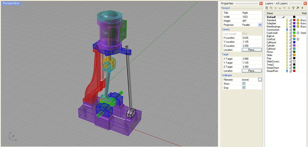
First thing to note is I have placed each part on its own layer. See the menu on the far right for layers? This lets me set each color independently and turn the layers on and off independently, making it easier to work on the parts individually.
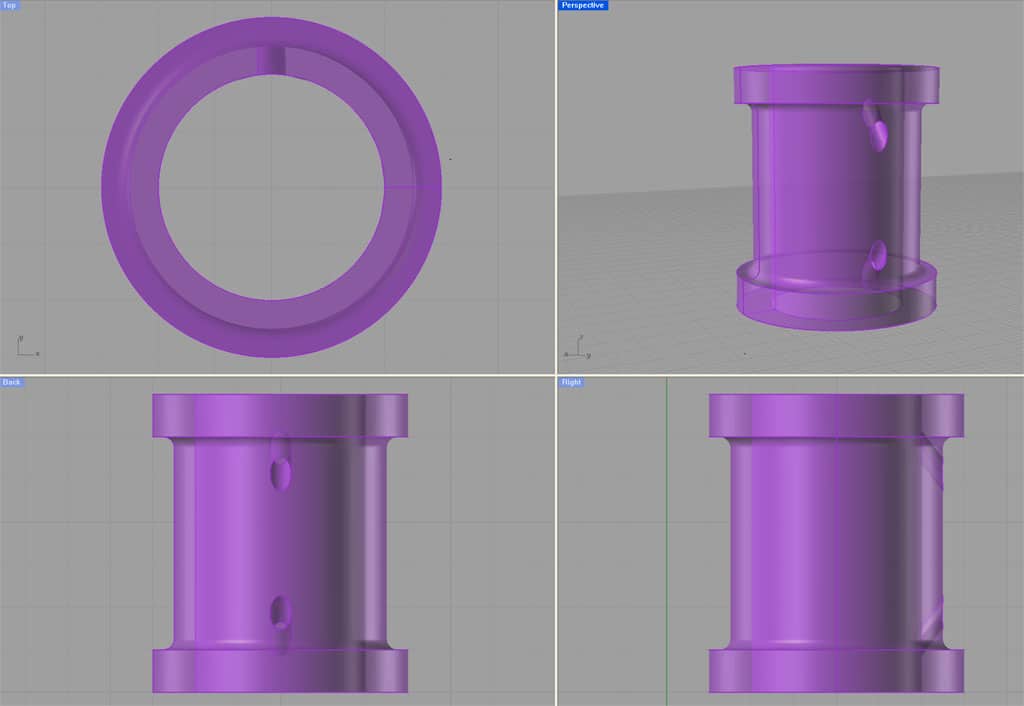
Here I have turned off every layer but the cylinder so I can see and manipulate it easily without clutter or damaging the other parts. You can see the steeply angled steam ports that I wnat to get rid of for a better idea.
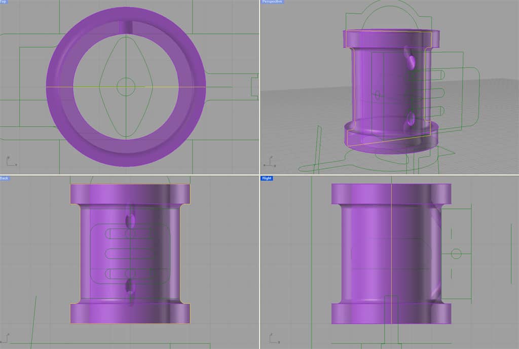
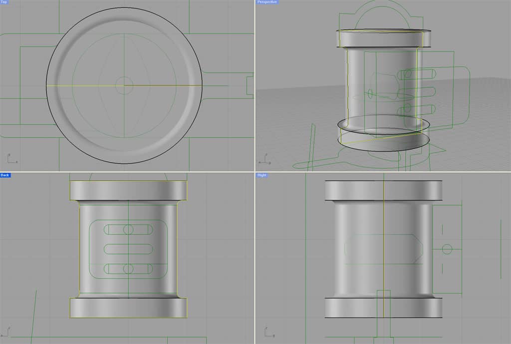
By convention, I keep a special layer I call "construction". It contains all the 2D lines I use when creating the 3D objects as well as other things. Normally it is turned off, but I like to be able to go back to the construction lines when I have to do something over. All the green lines are construction lines whose layer I just turned on.
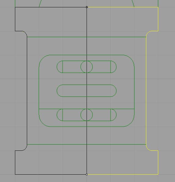
In order to "fill" the old steam port holes, I'm just going to remake the cylinder. Here is the original 2D profile I used to make the cylinder. You can also see some lines associated with the steam box.
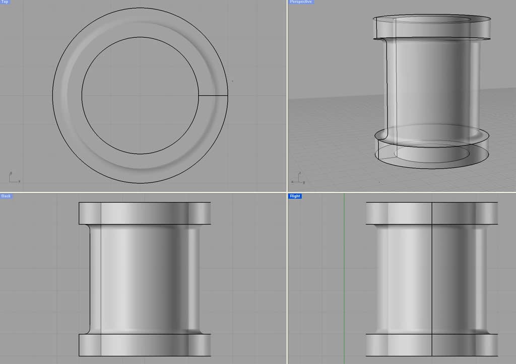
I use a command called "Revolve" to spin that profile to create a cylinder. It just spins 1/2 through 360 degrees. That half is lit up in yellow and the spin axis is shown as the black line with two endpoints at top and bottom.
Here is my newly spun cylinder!
Now I have to "bore out" the cylinder. I create a circle of the bore diameter and "extrude" that circle to make a cylinder. Think of the cylinder as a "drill bit" you want to use to bore out you cylinder.
Using an operation called "Boolean Difference" I can "subtract" the bore cylinder form the steam engine cylinder. You can see we now have a 1" bore in the cylinder.
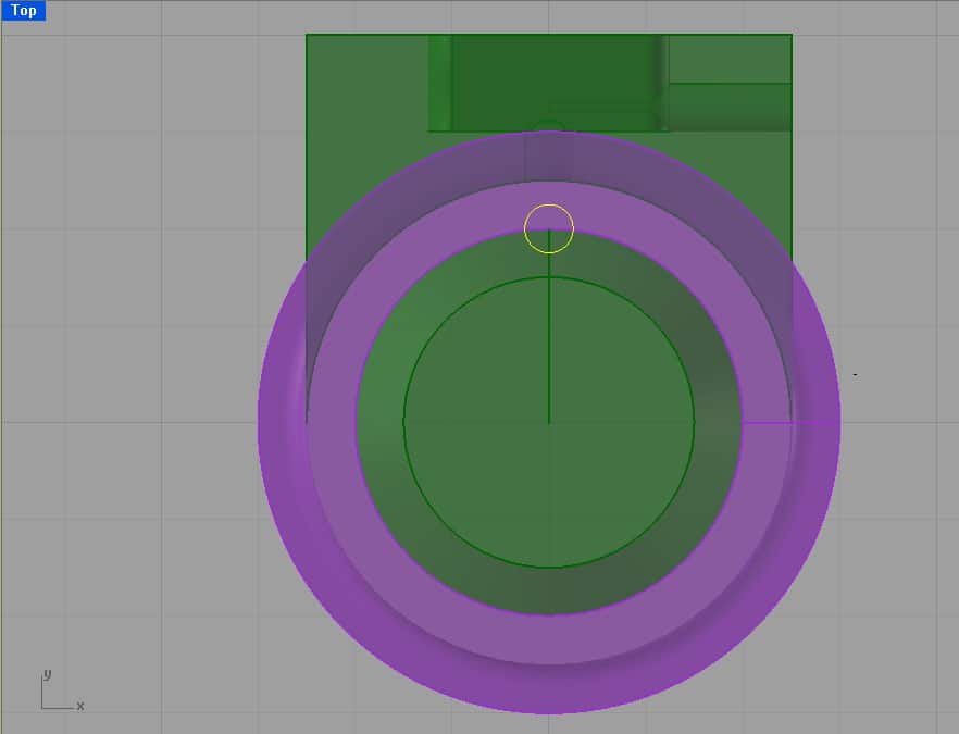
We're now ready to cut our new steam passages. The original suggestion was just to plunge an endmill to create a groove in the location shown. That would work fine, but I have the ability with CNC to do something fancier.
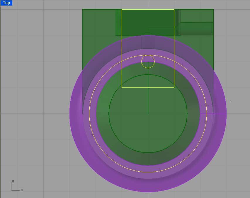
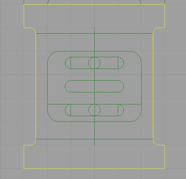
What if I take that 1/8" endmill and sweep it along the circular path shown within the confines of the rectangle that was created from the steam chest ports?
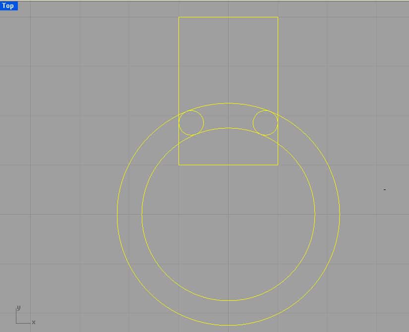
Here are all the construction lines. Note that Rhino made it easy for me to select the box and the two big circles and it figured out how to exactly postiion the small circles for me.
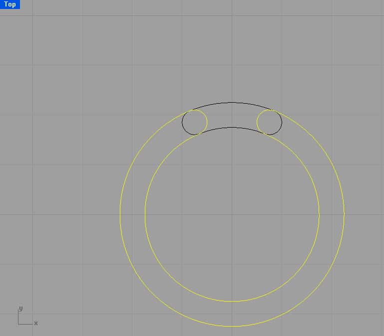
I mark and subtract the lines I don't need....
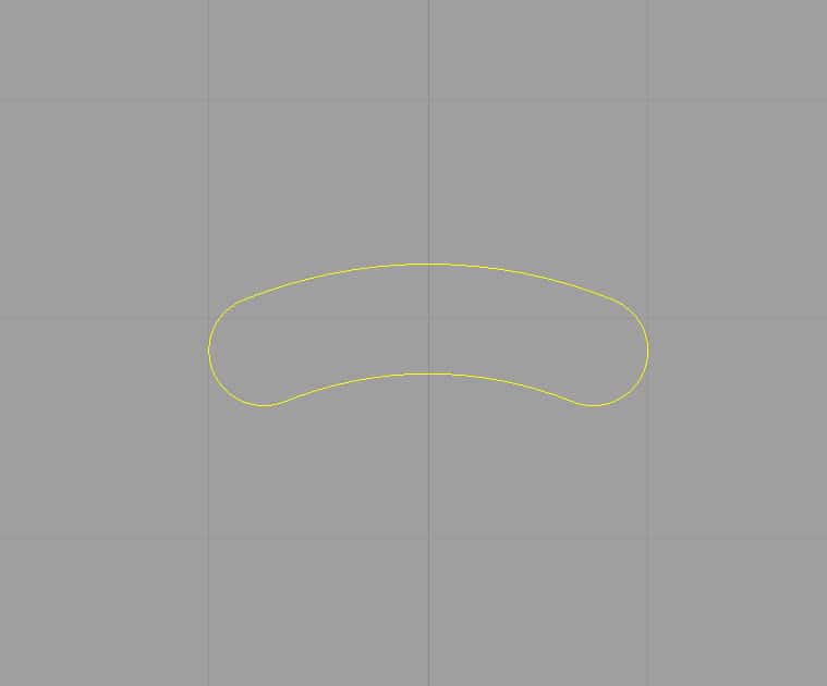
And here is the path the 1/8" end mill would take...
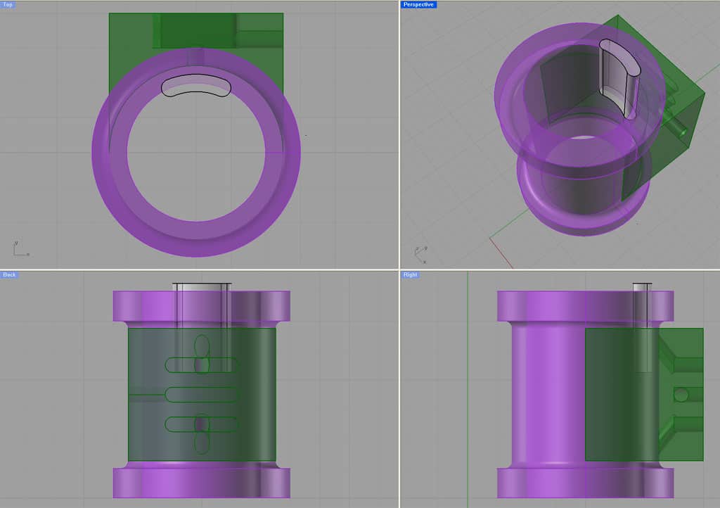
Now I extrude that shape up...
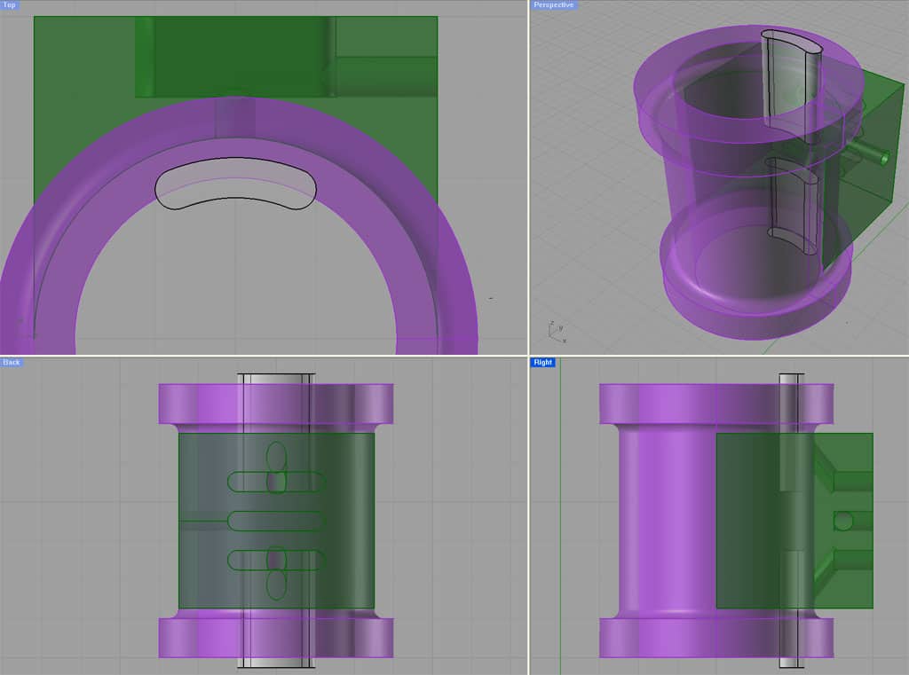
I copy another one down and properly aligned with the lower steam port on the double-acting cylinder.
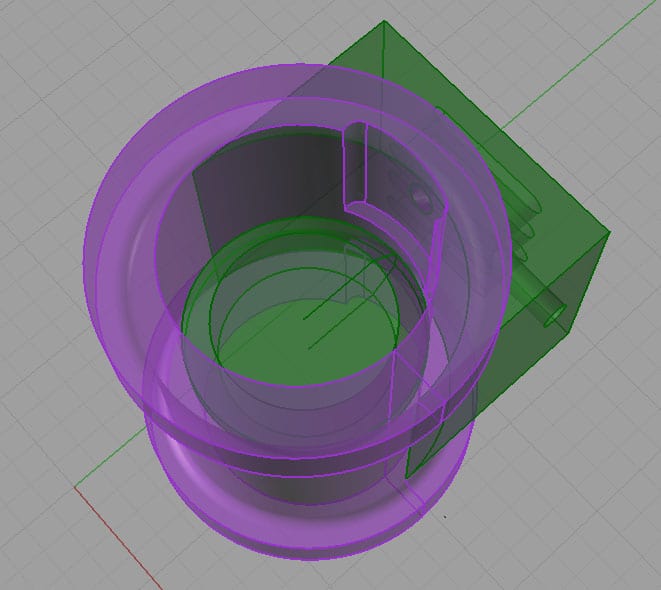
I do a Boolean Difference and voila! Now I have a Hot Rod Port job on my cylinder. Lots more surface area to flow steam than I had before. And the setup will be way easier than the angle hole drilling. I still need to open up the side where the steam chest goes, but I won't bother showing all that here. You get the idea!
Be the first to know about updates at CNC Cookbook
Join our newsletter to get updates on what's next at CNC Cookbook.