This is the second installment in our series on how to create a guitar design so you can CNC an electric guitar. In the first installment, we covered how to trace a photo to create an outline for the body. I also provide a set of outlines in a CAD file you can start from to save time.
In this installment, I'll show you how to:
- Size the outline properly for the neck pocket.
- Turn it from a 2D outline to a 3D model.
- Radius the sharp edges on the 3D model.
- Render the model to get an idea what the finished guitar body will look like.
Here's the second video:
Create a 3D model for a simple body...
Step 1: Size the outline properly for the neck pocket
Before we spend any time trying to convert the outline to a proper 3D model, it's important we get it sized properly for the neck pocket.
If you have a guitar neck you intend to use with the body, by all means, use its measurements as your starting point. You can save yourself a lot of time by buying a completely carved guitar neck that's ready to go.
Otherwise, I recommend you use the dimensions from a popular commercial guitar. For example, the dimensions of the neck pocket for a Fender Stratocaster or Telecaster is 2 5/8" wide.
The video shows how to take that dimension and scale the outline so everything is proportionally sized and the neck pocket is 2 3/16" wide.
Step 2: Extrude the outline to the proper depth
We generally convert 2D outlines to 3D objects through a process called extrusion. It's easily understood and faster to see it in action in the video than to spend a lot of time explaining or visualizing.
We actually need two steps.
First, we extrude to get to the thickness the finished body should be. You can choose whatever you'd like, but I chose to use the standard thickness of 2".
Here's the outline after extrusion:
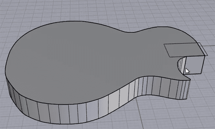
Here's the 3D model after extruding the body 2" thick...
Now we need to cut away the neck pocket.
This is easily done in 3D models by using what are called "Boolean Operations" between two solid models. Suffice it to say, I can "subtract" one object from another.
I extrude the rectangular outline of the next pocket to create a proper object to subtract with. The depth of the neck pocket on these guitars is 5/8", and that dimension is again something that's easy to look up on the web.
Here's the result after the Boolean Difference subtracts the two:
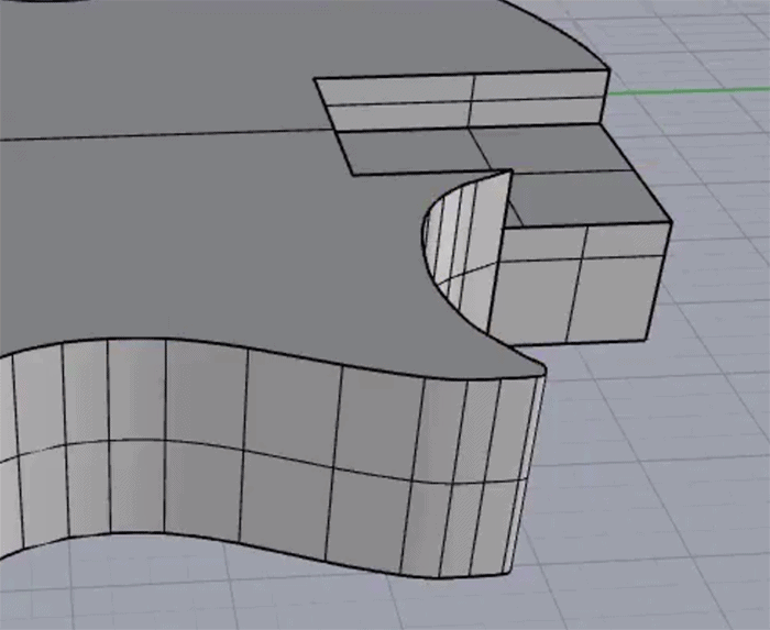
After Boolean Difference, we have a neck pocket...
You can clearly see how Boolean difference subtracted the template object and left behind a perfect neck pocket.
Step 3: Radius the edges
As I mention in the video, your next step is to decide how to treat the edges of the model. They're all sharp creases at the moment. There are two ways you could choose to CNC the edge:
- Use a corner rounding tool to cut a radius around the edge.
- Use 3D Profiling to cut the radius.
Our G-Wizard Calculator handles Feeds and Speeds for corner rounders, and they look like this:
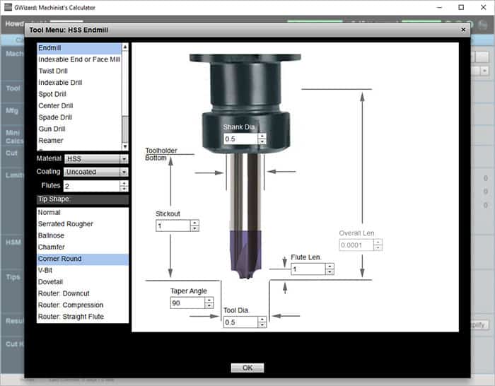
Corner rounding tool in G-Wizard Calculator...
If you want to use the corner rounder, then there's no need to radius the edges in the CAD model. In fact, it's better not to. You'll program a toolpath that puts the outside radius of the tool (part closest to the center) right on the edge and follows the outline to round it. In practice, you want to be probably just outside the outline to leave a margin for error.
But, you can also profile with a ballnose. It'll take a little sanding to smooth the profile, but not too much.
Putting a radius (or chamfer) on an edge is a pretty standard operation in most CAD software, and here's how it looks when we're done:
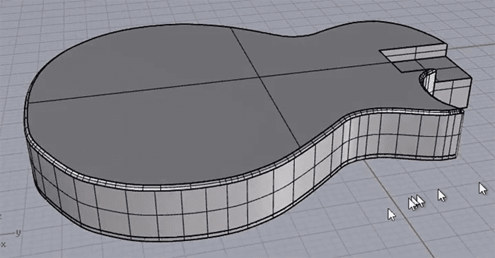
Radiused edges...
Note that we don't want to radius every edge, some want to be sharp-edged, such as most of the neck pocket edges. Be sure to think that through for your guitar design.
Step 4: Render so we can see the shape better
Great CAD software includes a rendering capability so you can see a more realistic rendering of your 3D model than the abstract views you use when creating the models.
Creating a rendering can be as simply as picking from a list of pre-defined materials that the model is made off, which is what we'll do here. But it can also get much more complex, involving backgrounds and defining what sort of lighting is to be used to illuminate the rendering. A good 3D rendering can look very realistic-more like a photo than a computer generated graphic.
Here's what our simple rendering looks like on our simple guitar body:
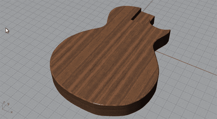
Simulated walnut rendering...
Conclusion
There's still more work to be done for a finished guitar. Specifically, we need:
- Holes to bolt the next to the
- Bridge mounting and pocket
- Pickup mounting and pockets
- Pockets for controls, wiring, and electronics
- Any other pockets or advanced features such as 2 part bodies (figured maple top and mahogany bottom, for example), lightening cavities, and so on
We'll get to all of those things in the course of this series as I intend to build at least one electric guitar body. But first, our next video is going to cover more sophisticated body modeling. This video shows a very basic body, but more complex bodies need more complex techniques. I'll cover exactly how to go about that next.
Be sure to subscribe to the CNCCookbook YouTube channel to catch the rest of this video series.
Be the first to know about updates at CNC Cookbook
Join our newsletter to get updates on what's next at CNC Cookbook.