Geof from CNCZone has constructed an impressively diligent project:
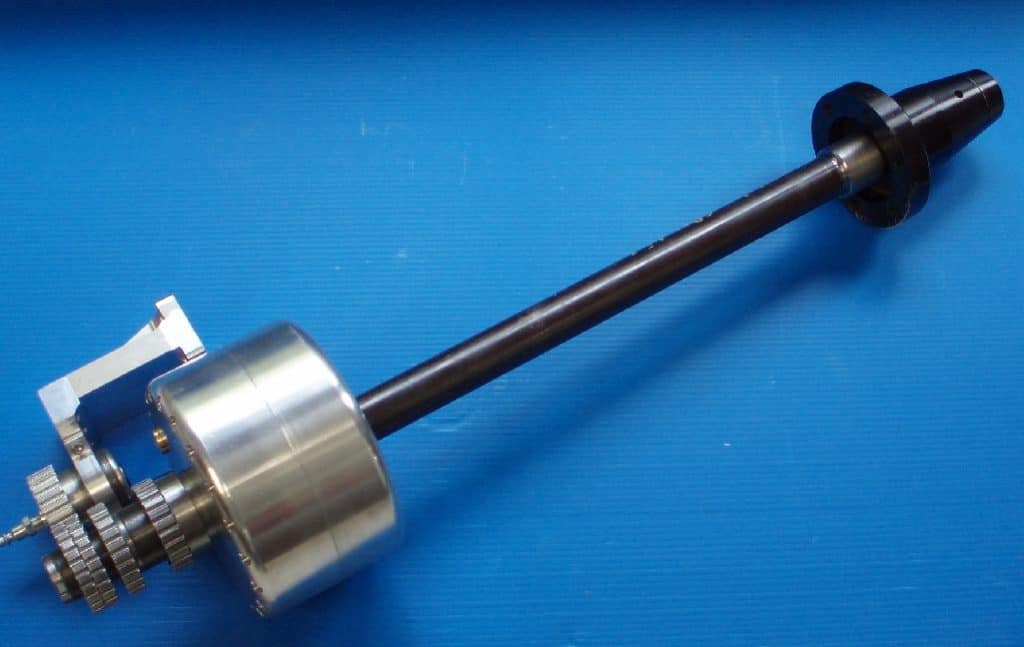
Air-Powered 5C Collet Chuck assembled...
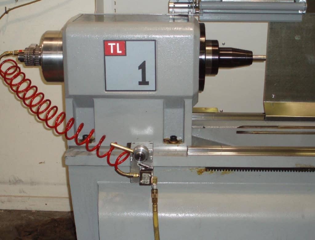
Installed on the Haas TL-1...
Some design notes:
Geof discovered the optimal draw force on the 5C system is about 1200lbs. This is accomplished via 10 springs that act to return the piston to the "locked" position when air pressure is released. The estimated unlocking force is up to 2300 lbs. Based on an air pressure of 85 psi, this calls for a 27 square inch piston. Since the piston is an annulus (donut shaped), the inner ring on the piston (so the bar can pass through the center) is 2.25 inches and the outer is 6.5". The whole thing is housed in an 8" OD cylinder assembly made of aluminum. Looks like a big o-ring is used to seal the piston against the cylinder and a smaller one seals the piston hub. These O-rings are standard sizes.
Threaded adjustments on the drawbar end control draw tube force, release free travel, and piston stroke. The release free travel lets the tube travel a short distance to pick up speed so it can knock the collet loose. Plastic liners protect the draw tube's interior from the bar. The tube is stainless with a 600 grit polish.
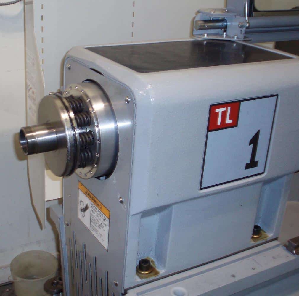
The provision to provide air is a novel design. Geof wanted to avoid designing a rotating seal, so the air is injected by temporarily mating the injector against an injection port while the chuck is not moving. The system is designed so there would be minimal damage if the spindle started while the injector was engaged. Note that the injector is not in the center, but offset, so the spindle has to index it into position before it can engage. Air pressure supplies the force to mate the nozzle to the port. All in all, its quite an interesting design. Given how expensive even lever operated closers are, let alone pneumatic chucks, I can see how one might undertake to build such a thing.
More detail:

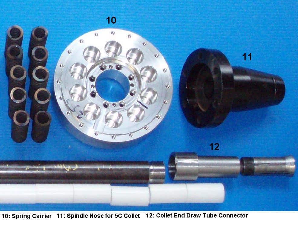
I need to make a nose with a D1-4 adapter similar to what's in use here for my Tormach Slant Bed lathe. The current arrangement puts the end of the collet flat with the flat area where a chuck would go. This doesn't leave much clearance for any tools that protrude from the turret for doing ID work such as boring bars and twist drills. A tapered nose like this one would help quite a lot.
Be the first to know about updates at CNC Cookbook
Join our newsletter to get updates on what's next at CNC Cookbook.