What is a G-code Viewer?
A G-code viewer reads a G-code file (also called an NC file) and shows you what it will do: a 3D drawing of the toolpath, plus information about the program that's hard to see by reading the code. It's the cheapest insurance you can buy against a broken tool, a ruined part or a crash.
If you want help choosing one, see our NC viewer buyer's guide. This page is about using one. We'll walk through checking a real program with CutViewer, the free browser-based viewer we recommend now that CNC Cookbook's G-Wizard Editor is no longer available. You can follow along with our example files.
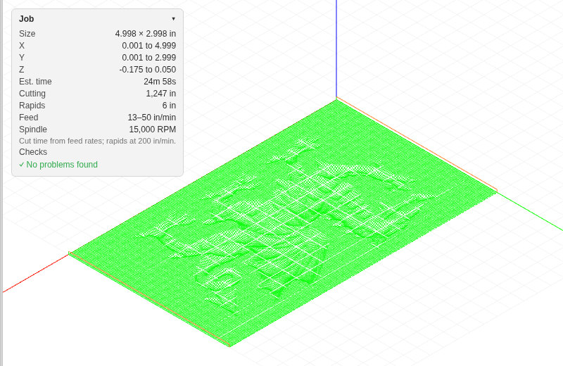
Step 1: Open the File
Go to cutviewer.com and drag your file onto the window, or click Open File. CutViewer reads .nc, .G-code, .tap, .ngc and other G-code files. The file is read in your browser; nothing is uploaded.
To follow along, open our Griffin relief carving straight from this page: open the Griffin relief in CutViewer.
The G-code appears in the editor on the left and the toolpath on the right.
Step 2: Look at the Whole Toolpath
Start with the big picture. Does the shape look like the part you expect? Use the Top, Front, Left and Right buttons, drag to rotate, scroll to zoom, and press F to fit the toolpath to the window.
The colors tell you what kind of move you're looking at:
- Rapids (G00) are the fast, non-cutting moves. Watch these closely; a rapid through the part is a crash.
- Feed moves (G01) are straight cuts.
- Arcs (G02/G03) are drawn in their own color.
Things to look for:
- Moves that leave the part area or go somewhere unexpected.
- Cuts that are deeper than you intended.
- Giant, almost-complete circles where you expected small arcs. That usually means your CAM and your control disagree about absolute versus incremental I/J/K, which our G02/G03 arc guide explains.
Step 3: Read the Job Panel
The Job panel in the corner of the 3D view sums up the program:
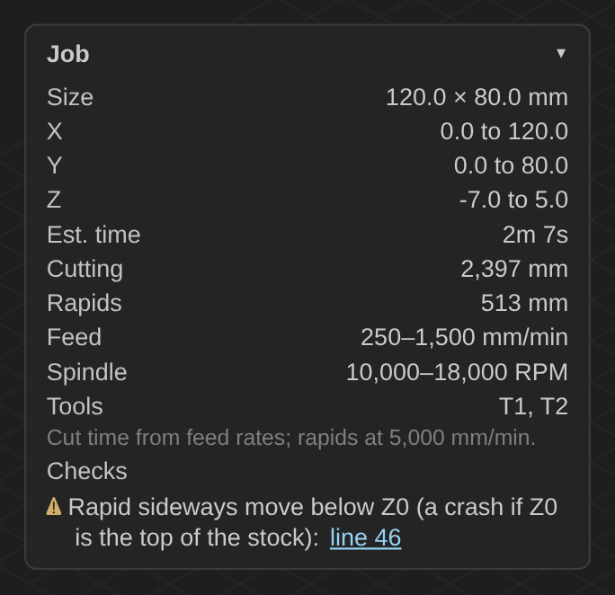
- Size and X/Y/Z extents. Does the part fit your stock? Does the lowest Z match the depth you planned? Is anything outside your machine's travel?
- Estimated run time, from the feed rates in the program.
- Feed and spindle ranges. A feed or speed far outside what you expect is a common post-processor or typing mistake.
- Tools. Make sure you have every tool the program calls for, in the right pockets.
Step 4: Check the Warnings
Under Checks, CutViewer lists problems it found in the program, with links to the lines that cause them. Those lines are also marked in the editor. It looks for:
- a feed move with no feed rate set, which most controls reject
- an arc whose end point isn't on the arc, which most controls reject with an alarm
- a cutting move with the spindle off (for example, a program that sets a spindle speed but never sends M3)
- a rapid move below Z0 into uncut material, which is a crash if Z0 is the top of your stock
- no G20 or G21 before the first move, which leaves the units up to whatever the control was last set to
To see one, open our home switch panel engraving. The panel is 11" × 4", but the program never says G20, so CutViewer flags it. On a control left in millimeters, every move in that program would come out 25.4 times too small. Read more about G20 and G21.
Step 5: Step Through the Program
Now look at the details. Press Play (or the space bar) to watch the program run, and change the speed with the slider. Drag the progress bar to jump anywhere. Click a line in the editor, or click the toolpath, to see exactly where the tool is at that point; the position, feed rate and spindle speed are shown below the 3D view.
Pay extra attention to:
- the first move after each tool change
- the plunge into the material at the start of each cut
- the retract and rapid between features
Step 6: Fix and Save
If you find a problem, you can fix it right in the editor. The toolpath updates as you type, so you can check the fix before saving. Click Save (or press Ctrl+S) to download the edited file, then load it on your machine.
For anything bigger than a small fix, go back to your CAM software so the change is in your source file too.
What a Viewer Can't Tell You
A viewer checks the program, not your setup. It doesn't know where your work offset is, how long your tool is or where your clamps are. Before the first run of any new program, still:
- double-check your work offsets and tool length offsets
- run the first part slowly, with your hand near the feed hold
- consider a first pass in the air above the part
Learn More
- Free G-code example files to practice on
- Our free G-code programming course
- G-code and M-code reference list
- How to choose an NC viewer
- The 8 best G-code viewers and editors
Be the first to know about updates at CNC Cookbook
Join our newsletter to get updates on what's next at CNC Cookbook.