Build a concrete milling machine? Almost, but with a little help from structural steel and a better vibration damping material than straight concrete. This design exercise was inspired by the Polymer Concrete thread on CNCZone.
Polymer Concrete is a technique of using epoxy resin with an aggregate added to it to create a material that is not as strong as a traditional machine frame, but that has excellent dampening qualities. There is more than one kind of Polymer Concrete, but one using Epoxy Resin and Granite Aggregate for filler seems to be quite good for these applications.
This material has been used to create machine frames commercially by various companies. After reading posts for a long while (they were up to 46 pages), I wanted to try my hand at doing a Rhino3D design sketch of a gantry-style machine that would use this material together with a weldment-based frame.
This construction approach is similar to the one Bamberg advocates in his PhD thesis "Principles of Rapid Machine Design." I highly recommend that document to anyone wishing to undertake the design of precision machine tools that do not require elaborate iron castings. Search it out with Google. I'd provide a link but I notice it moves around.
EG Table Pour Frame
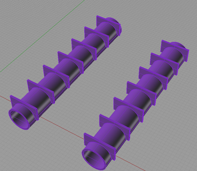
The table for the machine has a frame constructed of 3" diameter 1/2" wall thickness DOM steel tubing. The table surface is 48" x 48", but the technique could be scaled to a larger or smaller size. A 1/2" thick steel plate under the DOM serves as the bottom, and a framework of 1" steel rods is welded inside on a 1′ x 1′ grid to act as rebar-like strengtheners. I am postulating that all DOM tubing would be filled with the EG material for further dampening and stiffening. Here is a view of the pour frame:
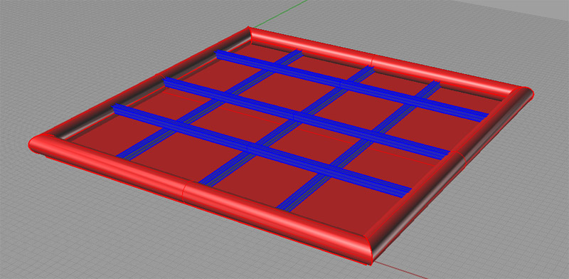
3" DOM Tubing and 1" "Re-Bar" Pour Frame...
I call it the "pour frame" because it will serve not only as a frame to hold the EG, but also as the mold into which the EG will be poured.
Insert Grid
Having completed the welding of the pour frame, the next step is to install the insert grid. The insert grid consists of pieces made of steel that have a threaded 5/16" hole at the top and a 7/16" cap screw threaded into the bottom. I have drawn them as constructed of 3/4" hex stock, but they could as easily have been round stock. I feel the hex will lock into the matrix better. To augment that and help prevent pullout, I have specified that grooves 1/4" wide will be turned into the stock:
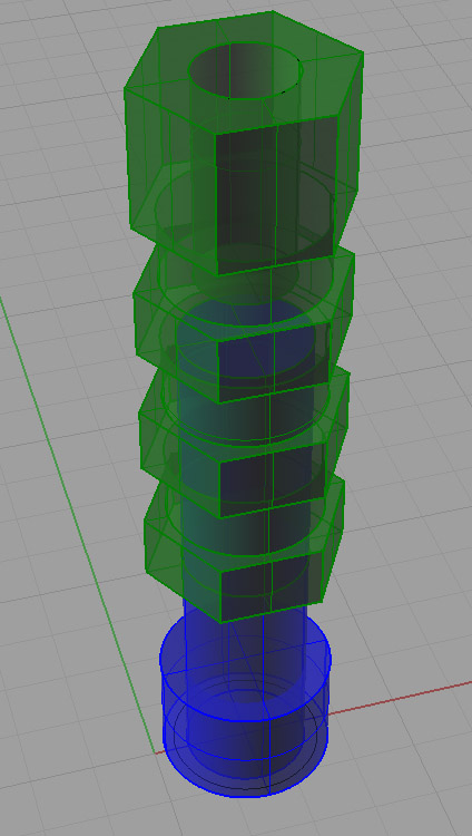
The insert assembly consists of the hex stock insert and a 7/16" socket head cap screw...
Aesthetics and Stress Riser Note: If you care how things look, it may make sense to turn the top 1/8" or so of the hex round. The hexes will wind up in different orientations as they are leveled, and if the top is round this won't be obvious once the epoxy is poured. Only the round portion will be visible at the top. While I'm on this topic, long time CNCZone contributor Geof has suggested eliminating the sharp edge from the inserts to avoid stress risers. That should be easy to do during the CNC operation making them. If on a manual lathe, I would think a form tool for the lock in grooves might be a good way to round off the edges while cutting the grooves.
We'll be installing the insert assemblies on a 2" grid within our pour frame. The 2" grid is a pretty common measurement I see for tooling plates in the CNC world. It gives you a close enough grid to bolt just about anything down properly on the table. We'll be using these inserts with their 5/16" holes for workholding as well as for mounting the linear slide system that will be used for the gantry.
One thought on these insert assemblies before I go further. Consider the issue of wear and tear on them. It would be reasonable to consider a couple of different ways to manage this. First, we could use some sort of hardened steel for the assemblies, which would help tremendously. Second, we can use replaceable threaded inserts that are commercially available for the purpose from outfits like Carr-Lane. Whichever approach is taken it also makes sense to keep flush bolts in the holes when they are not in use so they don't become a repository for old chips. I would suggest putting these flush covers in place before any epoxy gets poured!
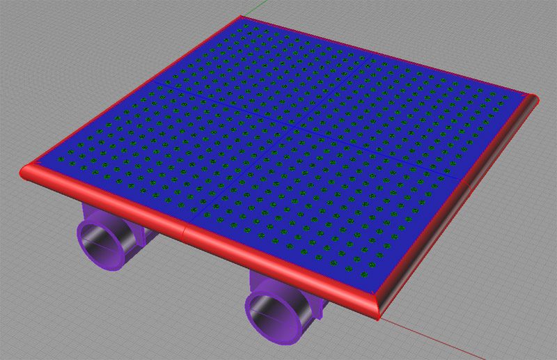
These pieces are installed by tack welding the SHCS screws to the 1/2" plate that is the bottom of the pour frame. We would make sure that each one is as close to vertical as possible during the installation process. When finished we now have a grid of these inserts welded into our pour frame:
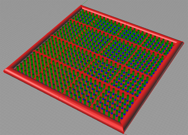
Pour frame with 576 hex inserts installed...
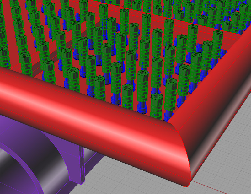
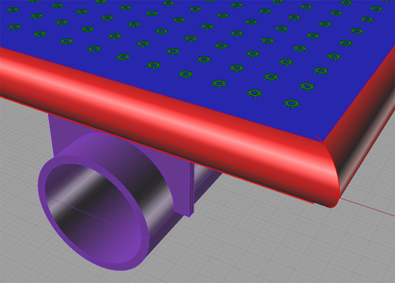
Close up on the inserts...
Fabrication Note: It's going to be darned tight getting your welding torch down into that grid with only 2" on each side and 3" deep! I recommend tack welding the insert assemblies to the 1/2" plate before the surrounding DOM tubing and 1" square "re-bar" is installed. At least then you can work from the middle out and access it from the edges to weld the inserts.
Support Sub-Frame
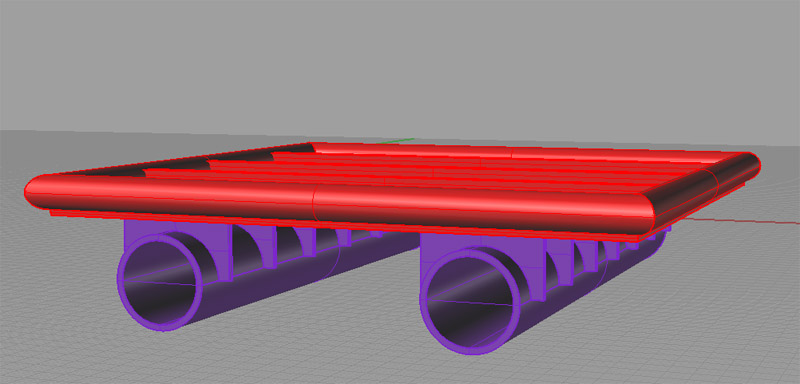
When we pour the Epoxy Granite mixture into the pour frame, the result is going to be quite heavy. That's a good thing, but there may not be enough beef in the assembly to maintain precision. Accordingly, I have sketched a support subframe that consists of further DOM tubing and weldment construction. It is made of 8" diameter 0.500" wall thickness DOM tubing and 1/2" steel plate:
8" DOM 0.500" Wall Tubing Sub-Frame...
The sub-frame very much follows Bamberg's approach for this sort of thing. It would probably be better with a cross-member to provide an "H" shape, but FEA analysis is needed to really prove out this whole design anyway. I would fill the 8" DOM with the EG mixture and a bundle of rebars spaced into a hex pattern and running the length of the tubing for additional dampening and strength.
Here it is with the pour table and inserts back in place:
The next step is to level the inserts.
Leveling the Insert Grid
We want all of the inserts to be properly leveled in place so that the finished table is as accurate as possible.
Note that this would ideally be done with the epoxy in place in the pour frame (and certainly it should be in all the DOM tubing!) so that any bending of the structure due to the weight of the epoxy is taken into account. I would like to see some FEA analysis to tell us how much flex in this structure there is likely to be due to the weight of the structure and the EG. This would give us some idea of how much we need to worry about it. Bamberg (remember that PhD thesis?) really likes the idea of aligning the machine and machining it while assembled so that the natural stresses are properly accounted for. Towards that end it will also be good to make sure the sub-frame and even support legs or any integral stand are in place before any precision leveling is attempted.
Given the curing process, that seems difficult to arrange that we can pour the epoxy and then get all of the inserts adjusted before its too late, but here are some thoughts:
- The bottom of the insert hex piece is an inch above the bottom plate in the pour frame. One could at least fill up to a reasonable adjustment distance from the bottom part, taking care not to get any epoxy on the threads. Be sure to leave enough travel for any flex in the structure. We want the inserts to wind up as close to flush with the EG table as possible. The epoxy will likely have to cure in layers anyway.
- After that bottom layer has cured, we can fill the remaining space with a suitable substitute that carries as similar a weight to the epoxy as possible, but that can be easily removed so we can pour the epoxy and that will let the inserts be turned freely for adjustment. Possibilities include the aggregate we plan to use without the epoxy, sand (to be vacuumed out later and used again as aggregate), or perhaps a heavy oil provided it won't damage the ability of the epoxy to set up properly when the time comes.
Putting that disturbing fly in the ointment aside for the moment, lets assume that we have simulated the weight and bending of the finished table as closely as possible. Our next step is to turn the inserts on their threaded cap screw mounts until they create a grid that is precisely level in the Z axis. As we pronounce each insert properly leveled, I propose to use a long nosed applicator to place some Loctite well down in the hole to lock the insert hex in place so it can't be knocked out of adjustment. Don't touch the inserts once aligned until the Loctite has set up!
It's clear how the screw provides up/down adjustment, but how are we measuring when we have the proper height? I have again had several thoughts on the matter. First, let's assume we've made a nice set of alignment cones that end in a 60 degree point perhaps 1/2" to 3/5" above the top of the insert hex. There should be a shoulder so that it rests atop the insert hex, and a locating dowel that extends partially down the 5/16" hole, but that is not threaded. I don't want unscrewing this alignment aid to upset the final adjustment of the insert, so one should be able to just pick it straight up when done. The tip of the cone is the reference point we will use, and if we make more than one of these, they must all sit at precisely the same height when resting on an insert.
Now how do we create a reference plane such that the tips of these cones are at precisely the same height? I've had two thoughts on this. One could invert a granite surface plate over a section (say 1′ x 1′ at a time), and simply adjust each insert until its cone contacts the surface plate. That actually seems very straightforward. My second thought is that there should be a way to use a laser to do this. There is probably some very clever way to bounce a laser off a mirror or sensor atop the cone and get the thing adjusted within a tenth, though I confess I don't know it. I'll leave that one as an exercise for the reader. Please send me an email if you have any clever ideas!
Time to Pour the Epoxy-Granite!
Let's review. We have created a pour frame and anchored it atop a solid sub-frame. The 576 inserts within it have been precisely aligned so that they form a level plane of points accurate to within 0.001" or better (preferably better!). We are now ready to pour the epoxy-granite mix and create the table!
It should be a thing of beauty once it cures:
Epoxy Granite Table with Inserts...
Now given what has been written about this miraculous Epoxy-Granite composite material, we should just have created an extremely rigid, extremely well damped, and accurate to 0.001" table on which to build the rest of our gantry mill. The 5/16" inserts provide a convenient place to bolt the railing system needed to carry the gantry, for example.
The amazing thing is that we should have been able to get this far with nothing more than a welder of some kind (mine's a Tig, but Mig would be the best?), a chop saw, a small lathe, and some basic measuring tools. I say it again: I would love to see what a Finite Elements Analysis would tell us about the likely performance of this table. With some tuning and iteration, I don't know why it couldn't be the basis for a very fine machine tool.
Some Precursor Experiments Are In Order...
Before starting on a project of this magnitude, I would be sorely tempted to create some test pieces. First I would work on casting Expoxy Granite with whatever aggregate I planned to use until I got that down pat. Then I would experiment with embedding a single insert assembly and seeing what it takes to get the pour right up flush with the top and a smooth surface. Lastly, I would scale down the big table size to say 1′ by 1′ but keeping the 2" DOM and 1/2" plate pour frame (no subframe for this prototype). This would make a reasonable set of test/learning experiments that ought not to be too time consuming or cost prohibitive. Assuming they came out well, you would have the experience and know-how to build a big (or bigger!) table like this one.
Vacuum Table?
I have postulated this design for milling metals, though it should work fine for other materials as well. it would be straightforward to substitute an alternative for the insert grid that would create an air table. One could embed a piping system on a regular grid. I would have the vertical pipes extend slightly higher than where the resin top would be. Once cured it becomes a simple matter to trim the excess with a high speed body grinder. A central outlet from the pipe grid could be connected to a shop vac or perhaps a compressed air venturi system to draw a vacuum.
Be the first to know about updates at CNC Cookbook
Join our newsletter to get updates on what's next at CNC Cookbook.