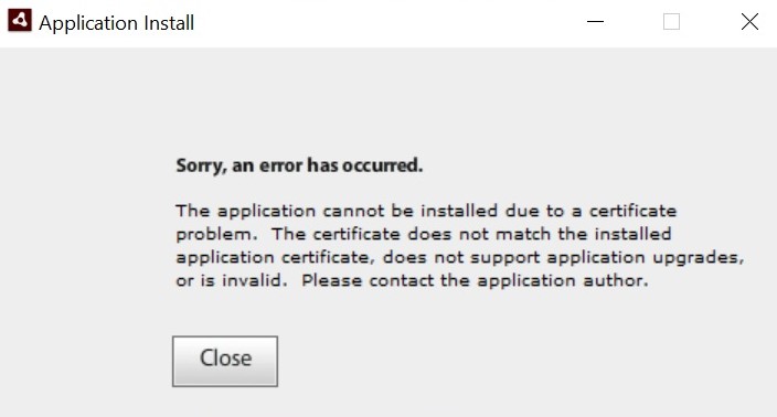
17 hours by cncdivi

Why CNC for a Home Shop?

There is a good discussion over on HMEM where someone asks why anyone would want CNC for a home shop. Their shop instructor told them that for less than 3 identical parts, manual machining could do it faster and cheaper. Here was my response:

First, I would not want to undertake CNC unless:

– I had a decent knowledge of manual machining. How to measure, what the cutting should sound like, how to judge if I’m going too fast and so on. You lose all “touch” with CNC and have to be able to rely on your experience more IMHO. As a home machinist, you can’t just be the “button presser” on your CNC. You are the designer, the one who comes up with the fixtures, and all the rest. Solid manual machining experience is a good background for that.

– I was comfortable with computers being a lot bigger part of my shop experience. This is inescapable when you go to CNC. In particular, you will have to deal with CAD, certainly the machine control (Mach3, for example), and possibly CAM software or g-code programming.

– I was comfortable poking and prodding my way through making the electricals work. There are a lot of electricals with CNC, and if you have a hard time changing a light bulb, you don’t want to be dealing with the frustrations of a CNC system. This doesn’t mean you need to be able to do component-level diagnosis of circuit boards, but you should be handy with a voltmeter and reading a circuit diagram. Like any machine, the CNC will break sooner or later and you’ll have to fix it.

Second, I don’t buy the instructor’s notion that CNC doesn’t “break even” until you need to make several copies of a part. There are a lot of advantages of CNC that are apparent very quickly if you have even a little bit of proficiency:

– It requires less tooling. By the time you pay for a nice DRO and power feeds on all three axes you can just about pay for CNC. Not quite, but close. Add up all the other tooling you may have that is no longer required for CNC and CNC will be cheaper. But, you’d need to pay that bill up front, so it may not matter. Also, to take full advantage, you may need to buy a CAM program so you don’t have to g-code it all by hand. That gets REALLY expensive and will eliminate most of the cost savings if not all.

– You can do things that just aren’t possible or would be very hard with manual machining. Complex flowing curves and engraving are two examples. We have ball turners for lathes, but profiling such shapes and much more complex ones is trivial with CNC. Also, there are operations that a really talented manual machinist can do that I can’t do manually, but can easily do with CNC. There is less of a burden on you, the machinist, to develop that fine art, but you will be called on to develop other fine arts.

– CNC can be faster. The CNC can whip out operations a lot faster than I can, at any rate. A big part of my impetus is this productivity. I simply can’t build everything I want to build in my shop fast enough eith the hours available to me. If I invest some of those hours up front in a CNC conversion, I can get more projects done later.

– Surface finish and precision can go way up with CNC. Did you experience an immediate improvement in surface finish when you got a power feed for your mill? I did. Can you hand feed on your lathe and get as good a finish as with the power feed? It’s really hard for me, and the results are not always reliable. Now imagine if you could dial in the perfect speeds and feeds for every operation via CNC. In fact, through features like CSS, the machine will even vary the lathe spindle speed as you move towards the axis to ensure that perfect cutting speed.

Let’s end my post by considering some photos. Here is a set of CNC’d pulleys hot off the machine:

Sorry, there is no text provided to rephrase. Please provide the text for rephrase.

Note the surface finish. How easily can you get that manually? Sure, some part of it is the radically better rigidity of the machine used, but some part is also the perfect feeds and speeds concept I mentioned.

Now consider a more typical HSM project, an upright marine style multiple expansion steam engine. This one was done in a home shop with CNC by jimmibondi (Frank) that won the HMEM November Engine of the Month:

I will venture to say that it wouldn’t take me three copies of it for this masterpiece to get done a lot faster and better with CNC than manual machining. Not that you couldn’t do it manually, and not that it didn’t require incredible craftsmanship to do with CNC, but it would just take a lot longer manually.

With all that said, manual machining is tremendous fun and CNC is not for everyone. It’s a hobby, do what you like!


12/31/08

The Eternal Servo vs Stepper Jihad Continues

There are a number of “Jihads” in the machinist’s world including the indexable carbide tooling versus hand ground HSS tooling debate, and this debate over the value of servos versus steppers in small CNC machines. I have used both and wrote a response when this subject came up over on the HMEM board recently. I thought I would pass along that response here so the points would be preserved:


Aha, the sacred Servo/Stepper/Open Loop/Closed Loop Jihad has made it here!

I have both. There are good arguments for both. In the end, I have a hard time not going for the servos if I can afford it. Just as we can say NASA used stepper-based systems back in the day so therefore steppers are good, we can also say there are almost no stepper-based VMC’s made today, so therefore servos are better. In fact, the servos way outperform steppers in most cases, they just cost more, and you may not need (or be able to take advantage of) that extra performance.

We can argue that we don’t care about that extra performance, and we may not, but let’s not kid ourselves that there isn’t even the potential for the performance or that it won’t matter to anyone.

I agree with most of what kf2qd says, but I don’t agree on the cost point. A servo-based system is more expensive, but it isn’t $1000 per axis!

For example, my IH Mill runs homeshopcnc servo motors at a cost of $235 (I got the fancier ones, but they have one with encoder for $199 if you’re pinching pennies) for 850 oz in motors, which are pretty stout. Equivalent stepper motor might be $130 from the same place, so you save circa $69, the cost of the encoder.

Add a Gecko servo drive 320 at $114, which is the same price as a Gecko 201 stepper drive, so no incremental cost there.

The last servo specific piece I use is a board from CNC4PC called the “Master Control Board”. It manages the servo fault signals from the Geckodrive and costs $48. You wouldn’t really need one with a stepper system, although it could be used to manage your E-stop and limit switches. The nice thing it does for servo users is it manages servo fault signals so that a servo fault looks like an E-stop. What does that mean?

A servo fault happens when the encoder indicates that the motor hasn’t been keeping up with the commands issued by Mach 3. On a Gecko 320, the fault is triggered if the encoder falls more than 128 steps behind the commanded position. For my IH mill, each step is 0.7 of a tenth, so an error of 128 means that axis is off by about 9 thousandths. Note that this will differ based on the leadscrew pitch, encoder counts, and belt drive ratios for your machine, but it gives you an idea.

In practice what happens is, I run the CNC program, and if the servos don’t fault, I know I was within 9 thousands, and probably a lot better, of what the program intended. Equally as important if not more so, the program may have gotten off by nearly 9 thousandths at some point, but with a servo system, it can “catch back up”, so the error is localized and doesn’t carry through all subsequent moves. If I was running a stepper system, I might be off by a lot more, and the errors become cumulative. Once I’m off, the system never catches back up again. In fact, if I start a whole new part without rezeroing, the error lives on for the new part too!

With the servo fault, I can see by where the machine stopped what it was doing when the error added up to too much. It’s pretty easy to turn down the feedrate (potentially just for that part of the program and not the whole program too), restart the program, and try again. If the same happens for the stepper, I have to start measuring the part to find where the error begins manually. I may not even be able to measure the beginnings, because they may have been machined off. In fact, with the stepper, I have no idea if there error is due to lost steps or some other source of error in the machine. This makes tuning up your programs a lot harder with a stepper system than a servo system.

It would be ideal if the controller could actually log where the errors occurred, how far off things got, and even let me set in software the servo fault limit (maybe I want to fault if its off by more than a thou, or perhaps I’d like to be able to change that tolerance at different places in the program). It’s be even better if the position signal made the control dynamically slow down or otherwise take steps to “do better”. I can’t really do that with the rig I describe. I can do a little better with the Rogers board, but it isn’t clear to me how to make that board work without even more encoders. It’s more of an add on to a stepper system. It’s probably not possible at this stage in Mach 3 development to do what I describe at all, but what I do get seems pretty good to me.

In practice, I suspect steppers lose steps a lot more often than most stepper users think. Many people complain that the Gecko 320 is “too sensitive” to servo fault. Given that the fault doesn’t happen until they are off a few thou at least and maybe more, those same people are obviously used to running stepper systems that silently get off by that much and keep going.

It can get a lot worse too. Servo faults can be caused because the program runs awry and the cutter is plowing into vises, clamps, tables, and whatever else gets in the way. The stepper will keep chugging through it even after the cutter breaks and there is a smoking ruin. It isn’t going to take too much of that sort of thing before the servo will fault and things stop.

So to conclude this rather long essay, do I insist only on servos? No, not at all. I have two machines set up for steppers and one for servos. I’m happy with each. I’m just saying that if I can afford the added expense of servos, I think they’re better in every way. I don’t see a down side to them other than the cost. That cost is quantifiable. On my mill, it has cost me an extra $210 to buy 3 servos instead of 3 stepper motors, and another $48 for the Master Control Board. I think the extra $258 was well worth it on this mill. Your mileage may vary!

In response, John Stevenson makes some excellent points that are a good addition to my post:


First a couple of clarifications.

Yes the Bridgeport’s did have massive steppers on them, got loads lying about here and they were only 850 to 1200 oz in on a type 42 motor. Modern type 34 can piss all over these so it’s not the motors. the Bridgy controller / driver unit was absolute crap. This is the reason why there are so many good mills out there, they never wore out because they spent more time broken down, crash one into something and it burnt the output transistors out – full stop. They were only full stepping and could hold 0,001″ but even in those days 1 thou to NASA was still the same thou it is today.

Bob put some good points about the difference between steppers and servo’s and I have no beef with his explanations, they are 100%.

One point that has been missed though and lets face it this IS a hobby forum is the skills needed to built both systems. Steppers are cheap and simple easy to mount usually on existing hardware as they develop maximum torque at low revs. Servo’s develop max torque at high revs meaning you have to gear an axis down to get any sort of power out of it.

Quoting max feed rates isn’t everything in CNC as any G00 moves are not cutting and only costing you.

The main difference for a beginner is the complexity of the servo system. There are not many good servo drivers out there for one and all rely on encoder feedback, to a beginner this often also translates to noise. Read the CAD_CAM_DRO list, Gecko list and CNC Zone and most of the beginners problems are caused by electrical noise.

There is also a missing link at the moment in that the larger servo motors require analogue inputs but affordable controllers use step and direction, Gecko drives can’t power the big servo’s like the BOSS 2’s and Mach can’t power the larger Fanuc, Baldor and Siemens servo’s drives. Rutex tried and failed, the Pixie convertor card whist seeming to work was withdrawn so there is a gap.

CNC like any new venture is a steep learning curve and the sooner it flattens out the sooner you actually start learning and enjoying. Doing a simple stepper system to cut your teeth on and then progress if far better than throwing yourself into the top end, never getting a grasp of it and then feeling let down.

Incidentally my big mill, a Beaver, the same size as a BOSS 2 and built with the same stepper motors as the BOSS 1’s at 850 ox in direct onto 0.2″ pitch ballscrews has been running all day today drilling circular hole patterns with a 2.5mm drill. These holes are virtually touching and any errors show up immediately, add to this the machine has graduated dials on as it shared some components with it’s manual stablemate so when it goes home it’s easily checked. Todays run was 11,208 holes and it’s parked back on 0,0,0 two drill used, tomorrow it will be doing the same but different job and on 3.12mm holes.

I think my personal conclusion on John’s comments, which I stated on the board, is that it may be better for first time CNC’ers to try steppers and avoid the complexities that John is worried about.

In any event, I thought the discussion was excellent and the points were worth repeating here.

12/29/08

Clamping German Style With a Tooling Plate

From the same German site as the flycutter above comes this method of clamping very irregular parts:

The clamps go down the tooling holes…

German Steam Engine: Wunderbar!

All that fly cutting and other work (check out the article, it’s really good!) results in this absolutely gorgeous steam engine model with working water injector pump and flyball governor:


Governor connects via linkage to valve below…

12/27/08

Tormach vs IH Base Castings

Interesting to compare the two. Here is Tormach:

Here is Industrial Hobbies:

Looks to me like the Tormach is a little beefier. I’m glad I did an Epoxy Granite fill on my IH; I’ll bet it’s beefier still! I’m also glad I’ve got those big ole hockey puck leveling feet to help me adjust. OTOH, I may just find my base is so stiff that shimming it won’t adjust a twist out at all and I’ll need to shim the column instead!

Shim or No Shim for Twist on Lathes and Mills

One sure way to ignite a controversy is to bring up the topic of leveling as it relates to out of square lathes and mills. There is a school that says you level the lathe’s bed and the rest is a function of the machine itself. There is another school that wants to use level as “close to correct” and then run a test bar with further adjustment of the leveling until the lathe cuts without taper. The first school sees this as adding a twist to the bed and is horrified. The second school sees it as a practical solution to a problem and wonders whether the first school realizes that.

Recently the same sort of argument broke out around milling machines, specifically the Tormach. It’s an interesting thread, with both sides weighing in. Philbur addresses the purest camp clearly with this remark:


I think that shimming the bed must be the last resort, not the first, for correcting a tram error. Tramming the table tells you that the spindle is not perpendicular to the table surface (assuming the surface is flat!), it doesn’t tell you why. The column may not be square to the table, or the spindle may not be square to the column, or both. Twisting the bed will most probably mask one error by introducing a second error. The correct method is to identify each error individually and correct it without influencing any other alignments.


OTOH, no less an authority than Tormach’s Greg Jackson himself says to shim the base instead of the column:


When working to optimize the left/right tram, shimming the front left or right feet under the base is always the first thing to do. The natural assumption is that the stand should be flat and rigid, then you put the machine on it and everything is perfect. The reality of the world is that everything is flexible, even those things that appear rigid. The stand is less rigid than the base of the mill itself and when the 1100 lb mill is placed on the stand, the stand moves a few thousandths of an inch in reaction to the weight of the mill.

Machine geometry can seem straightforward, but it becomes complex when you start to understand the fine details. If you take a perfect machine an put it on a stand which flexes in a non linear fashion under the weight of the machine, then there will be some left/right tram error due to a small twist force on the base. Countering that twist force by shimming the base/column connection point is possible but shimming between the base/stand is easier and probably a more accurate way to correct.

The iron base of the mill goes through both a heat soak stress relief and a vibration stress relief process so residual stresses are unlikely. The stand is a welded fabrication and will always have some residual internal stresses. If some alignment issues show up over time it could be the result of a crash, motion in the iron, or motion in the steel stand. We believe the stand is the most likely source. In the actual manufacturing process each machine base is checked on a large surface plate before the machine is assembled. Assembly and test is not done on a surface plate, but the rather on a three point stance. Instead of sitting on the four corners of the iron base, the machine rests on the back two corners and a round bar in the center front. Since three points determine a plane, this approach ensures that there are no stresses introduced in the machine base during the final test.


I’m with Jackson on this one from a practical standpoint, although he has sent me correspondence claiming that all problems with out of squareness can be traced to a stand that is not level, something I don’t agree with. It may be that the base is fine and the column could be shimmed, but if you can do it from the base, that seems an easier/better approach. If nothing else, try it that way first and take some measurements with your DTI to see how close you’re coming.

Also note that for this to work out well, you can’t bolt the machine to the stand. What you’re doing is using leveling feet on the base to jack one corner or another, so the base has to be able to rise and fall relative to the stand.

Some Random Surface Finish Tips When Milling

  • Keep a fine finish pass. Use a different cutter than you roughed with for best finish.
  • Keep your finish and rouging cutters separated. If you use the same type of cutter for both, start new cutters as finish cutters and move them to roughing after a little while.
  • If the finish is down a hole, relieve the upper cutting surface so it won’t be in contact with the hole and just cut at the bottom. This will reduce chatter, and works well when profiling with ball nosed end mills as well.
  • Use a larger diameter cutter, if possible, as it will flex less.
  • Keep the gibs tighter for less chatter.
  • Make sure the z gib is tight by lowering the spindle on a aluminum block on the table to put a bit of upward pressure on the head and tighten the gib on my x4 i was able to turn the screw of the z gib by a turn and a half this will reduce most if not all the chatter you might get from the head assembly.
  • I’ve seen Widgitmaster use a spacer to lock the quill on his Bridgeport. I try to cut with the quill locked on my Industrial Hobbies machine whenever possible.
  • Try a 4 flute on aluminum for the finish pass. By the time you’re ready to finish, there should be ample room for chips to fly and the extra flutes and light depth of cut will make for a nicer finish (the equivalent of more spindle rpm with a 2 flute).
  • Lots of folks swear by 3 flute cutters on aluminum.
  • Balance the diameter of a ball end cutter versus the rigidity. Remember, the part of the ball near the axis moves slowly. A smaller ball interpolated exposes more of the surface to a faster moving cutter, leading to a better finish. But, the smaller cutter can flex more. Hence the need to balance these two factors.

A couple notes on improving boring accuracy in a CNC mill:

More Boring Accuracy


  • Reduce the flex in deep holes on a 2 flute cutter by grinding down one flute. Now the cutter acts like a boring bar.
  • Interpolate the hole with the largest endmill that fits (to reduce flex) and leave a small amount for a finish pass with a reamer.

Stabilizing a Round Column Mill Drill

I have not been a fan of the round column mill drills because every time you raise or lower the head, it can rotate a little on the column. This means you lose your position every time you move the head. When I think about how often I crank the head up and down on my Industrial Hobbies mill, the idea of this seems extremely painful. I’d be tempted to go with one of the little Sieg mills of less capacity rather than deal with it. Nevertheless, these mills are quite popular, they are cheap, and a lot of very fine work has been done with them.

There are some potential solutions to the weakness of head rotation. First, I have seen cases of fixing a laser to the head and using it to align. If you can align the spot on a wall 20 feet away to a precision of 0.100″, your head will be accurately positioned to just under a thousandth. Mind you, I’d be tempted to use a wall 10 feet away and a reflector to put the laser spot somewhere close to the mill, but it could be done.

Another approach involves physically changing the mill’s structure to hold the alignment. I recently came across a fascinating thread in CNCZone where a fellow has built a wishbone stabilizer for just this purpose. Here are some photos:

The last photo shows an indicator in the chuck being run up and down a straightedge to test how accurately the head is held by the wishbone stabilizer. He says it swings as much as 10 thousandths while cranking but settles back down to 3 or 4 thousandths at the end. That’s not bad. I’ll bet there is a lot of play in the ball joints and there should be a way to build a little stronger wishbone that would be even more accurate. Nice write up!

12/21/08

Automatic Tool Change for a Small Sieg Mill Using a Compressed Air Kwik Change

This fellow had a stroke of brilliance. Follow on these pictures screen captured from his video:

Straightforward looking tool changer uses a Bimba cylinder that cost about $4 surplus. The lever gives it mechanical advantage over the die spring…

Size of the top of an R8 taper…

Size of a compressed air Kwik Change. An idea is born!

The top of the R8 taper is sawn off. This style taper is probably only suitable for small mills. That part we’re sawing off is probably a good thing on a bigger mill. Nevertheless, by cannibalizing an R8, he guarantees a huge selection of tools to modify…

Now clean up the taper on the lathe…

Tap it for a retention knob…

Knobs are made by turning the head of a bolt into a retention knob. This would be painful without CNC on the lathe I think!

A couple of modified tool holders for comparison. Wonder why he didn’t just use the air couplings? Probably that brass is just too weak compared to a bolt…

Drawbar and retention ring.

Here is a shot looking up the spindle. The retention ring is what forces the release when the drawbar presses down on the Kwik Change…

Die spring end of the drawbar…

11/21/08

A 2-Jaw 3-Jaw Chuck: Road to an Eccentric Chuck?

This idea from Practical Machinist intrigued me:

You can see they’ve modified a 3-jaw chuck with soft jaws to act as a 2-jaw chuck. The 2nd jaw is fixed in position with enough clearance that the 2 jaws not in use can still move. The chuck was made for working on this part:

It’s an intriguing solution, but the whole rig is pretty unbalanced as you could imagine, especially with such a big heavy part in the jaws.

But I’m wondering if it could be the basis for a specialized eccentric turning chuck. Imagine if that fixed jaw had a movable jaw that could be adjusted to create the offset with a precision screw and then locked. You would then have a quick way to load multiple pieces already set up for eccentric turning.

Very Nice Spindle Spider for a Lathe

Check out this gorgeous spindle bar support system I found on the Chaski board:

The different sized bushings are held in the spindle by the friction of their o-rings. Personally, I’d like a little more positive locking action, but the basic style is very nice and a good idea to prevent the bar whipping as it spins. I’ve got to add this to my project wish list.

11/15/08

Everyone Should Have an Air Shear!

<I initially misidentified the air shear as an air nibbler, but a thoughtful reader sent an email correcting me.>

I did those cutouts below by drilling a hole in each corner of the cutout and then connecting the dots with my air shear. The drilling was done with an air tool as well–love those air tools!

The cutouts were made by drilling a hole in each corner and then connecting the dots with an air shear…

The air shear has hardened jaws and went through the thick gauge steel box like butter…

A shear can be steered a little bit, but the tend to want to cut in a straight line. They curl up the chip vertically. The biggest issue is that sometimes that chip can push on the top of the shear and prevent the jaws from cutting further. The cutting action only happens along a very short length of the jaws. It helps to work the shear when it gets stuck. First try raising the handle to bend the chip out of the way. Then try rocking the shear on either side. That’ll clear it 90% of the time. Sometimes you have to grab the chip with pliers and bend it up out of the way further if all else fails. I was surprised at how easily the shear cut through the thick gauge steel on my box.

Everyone needs a shear! Mine is just a cheap Harbor Freight model, but it works great.


11/5/08

Air Muscles: A Cool Robotics Power Source

I recently came across the Shadow Robot Company thanks to a post on HMEM. They do a lot of cool things, but among them is a robotic hand powered by air muscles. Air muscles are simple to construct. They’re simply rubber tubes (such as bicycle innertube material) with a connector at either end. Pump air into the tube and expansion in the tube causes contraction of the muscle:

Air muscle contracts when air is pumped in…

According to shadow, a large 30mm diameter air muscle has a pull of 35 kg (about 70 lbs) at 3.5 bar of pressure, which would beabout 50 psi.

10/29/08

Evan’s Tubing Bender

While on the subject of Evan, here is a tubing bender he made for his shop that’s pretty nifty:

A Slotter for the Lathe from Canada

Here’s a really gorgeous slotting attachment for the lathe made by Evan Williams:

Lots to like about this slotter aside from the meticulous craftsmanship. For example, plenty of leverage on the handle, and the disc arangement on top gives different stop positions for the bottom of the stroke.

There are slotting heads available for mills:

Bridgeport Slotting head…

Why don’t we ever see slotting attachments mounted to the side of a mill spindle? One similar to Evan’s could be permanently mounted and available for use at any time without the need for setup on the lathe. Moreover, a small motor and you’d have your own slotting head equivalent.

My last thought for CNC’ers is that one could use the motion of an axis to drive the slotting action. I would not want the broaching force acting on my spindle bearings, but imagine being able to mount a tool on the side of the mill head nad use the Z axis servos to run the head up and down.

10/05/08

Make Your Own Transfer Screws

Full details here on making a set of M8 transfer screws:

Easy to make, but indispensible!

I needed a set to locate the holes in this plate for mounting the oil pump on my mill…

Not done yet, but it’ll go something like this…

10/02/08

Upcoming Sieg CNC Lathe

Some nifty photos of the upcoming Sieg CNC lathe:

Nice compact package with a modern enclosure is really neat!

Single shot oiler and a 4-position turret. The turret stepper interferes with the tailstock it looks like…

Spindle bore access and cat hidey hole!

They plan to sell these for education, but I can see a use for the hobbyist too! I’d love to get my Lathemaster 9×30 looking something like that.

World’s Best Snap Ring Pliers?

I always take note when someone starts a “best tool X” thread on one of the boards. This time around it was about snap ring pliers on Practical Machinist:

I have the usual type that has a single multi-purpose handle with interchangeable tips. I hadn’t ever really thought much about them, they work pretty good, but they flex, and sometimes that ring goes clear across the shop if it slips off the points. Lately I have been installing some pretty large snap rings (over 1″, which is large for me) on my CNC conversion for the millThat flex is a lot worse with all the tension and so the article caught my eye.

I really liked the Northern Tool set that had individual snap ring pliers in each configuration, and no interchangeable points. I can see where a lot of the flex in my current pliers is because they’re trying to be a snap ring Swiss Army Knife.

I took a look on the day I read about them, but didn’t pull the trigger. This morning I got a notice they’re having a small sale so I went back over and sure enough, the pliers were marked down a bit. The set is $49. It’s not a screaming bargain, and it is a bit of an odd tool, but, I ordered a set because I’ve never regretted a nice tool, even if I use it rarely. I see more snap rings in my future making up my own items anyway, so I also ordered some assortments of snap rings, hair pins, o-rings, and roll pins.

Here’s the set right here:

9/30/08

Vertical Stop for Milling

Vise stops are really handy things for saving you work. Set the work up once against a stop and you can flip the part to take advantage of symmetry or stick a new part in against the stop and keep going without realigning the mill. I made one that I use constantly, and I use small Kant-Twist clamps as stops as well. But I never thought of creating a vertical stop until I saw a thread on uses for 1-2-3 blocks on PM.

This fellow needed to run a corner rounding mill over a bunch of parts with different thicknesses. Rather than painfully set up the depth of cut for each thickness, he came up with the idea of using 1-2-3 blocks and a cross bar to create a vertical stop. He’d use one hand to raise the workpiece against the crossbar while making sure the crossbar was firmly down on the 1-2-3 blocks, and then use the other hand to tighten the vise. Here’s his sketch of the setup:

Clever!

9/27/08

Faceplates for Eccentric Turning

Over the years, some people have built special fixtures to make eccentric turning easier. It’s common when building engines and other projects to have to do eccentric turning to create cams or crankshaft offsets. Here is one such faceplate that accomodates either a flat tooling surface or a v-block to hold the workpiece at various offsets from center::

See my page on Eccentric Turning for more on these sorts of fixtures and practices.

An Automatic Bar Feeder for a 4×6 Bandsaw

I’m fascinated by all things “automatic”. I don’t know why, as I’m not running a manufacturing facility, but somehow these things just attract me. Here is a marvelous air-powered bar feeder for a small bandsaw that I found on the Chaski Boards:

The overall feeder

Feeder clamps. Cylinder on right is fixed. The one on left is on a sliding bed. To feed, release the right, clamp the left, and slide forward. Clamp the right, release the left, and slide back. That’s one cycle. Here is a video of the feed cycle:

The air cylinders are actuated by SMC air valves, and the overall automation is controlled by an Allen-Bradley Micrologix 1000 PLC.

Is that cool, or what?

A Tribute to John Bogstandard

I’ve put together a bit of a tribute to the model steam turbine work of Bogstandard, who has contributed a number of articles on the HMEM boards. John is another of those rare guys who not only does fabulous work, but shares his methods in a way that makes it possible for all to learn. One of the most fascinating areas John worked in was that of model steam turbines. I’m quite sure I hadn’t seen such a thing before coming across Bog’s engines, but they sure look fun:


Visit the Model Steam Turbine Page for More Info…

At some point I shall surely have to try my hand at making one of these beauties!

9/23/08

Liquid Tite Conduit

The conduit used here is called “Liquid Tite” I believe. Makes for a clean installation!

Cruel Teaser Sketch

Just the one “spy” photo of a little something I’m designing:

Curious how there are two different kinds of tool holders, eh?

9/14/08

German Epoxy Granite Milling Machine

Here’s an awesome project I recently heard about on CNCZone:

That machine is solid!

A few details I gleaned from one of the articles on the German site (you have to register!):

The epoxy granite mixture being used is 30% granite gravel, 30% joint sand, 30% fine quartz sand, and 10% R L & G epoxy resin. Based on my research, that should make for a fine epoxy granite base. And here are some interesting build pix:

Original Drawing…

Table/Saddle Will Be Incorporated into the E/G Matrix…

Mold for the base. This base will be case upside down. Note the screws sticking up from the metal parts–that’s how they’re anchored into the epoxy matrix…

The Epoxy Granite Has Been Poured Into the Mold…

Looks Promising! Wondered how he would get it to release. I like the use of melamine. Probably a release agent would make the mold reusable…

Front of the base. Note the precision steel pieces cast in place…

And the rear…

Painted and assembly underway. The Y-Axis mechanism is under the column. That much solid epoxy granite has got to make for a more rigid machine than the normal hollow cast iron!

Extremely clean electronics chassis…

Note the built in light! Looks like that will be the enclosure. Another nice piece of work…

Not sure of the taper. The text mentions SK30. That’s a release button on the side, so there must be a compressed air drawbar with bellville’s or some such…

Sample part: a lathe slide for an Emco 5. The original he says was warped. The new one is cast iron…

What a spectacular project!

9/13/08

Widgitmaster Mini-Routers Are For Superheroes Too!

On CNCZone is a fellow making superhero costumes with the aid of his Widgitmaster mini-router, and boy are they cool! Check out this resin part for an Ironman costume:

That fabulous finish came about in 4 passes: 1/8″ rough cut bit, 1/8″ parallel finish 10% step, 1/8″ parallel finish 5% step but with the part turned 90 degrees, and 1/32″ finish with 10% stepover. Apparently it took 6 hours, but dang, what a finish!

Check this talented Australian’s site for more info on costume making.

9/10/08

Gorgeous German Four Stroke Model Engine

I found this beauty by way of the excellent Chaski site. This engine is powered by butane and includes such nifty features as a centrifugal speed governor and a water pump to circulate cooling water.

Rigid Tapping Spindle Speed Accuracy

The question of rigid tapping comes up often in CNC. Can I chuck up a tap in a rigid holder and tap holes successfully? In theory, if we can move the tap vertically in a manner synchronized with the rotation of the spindle, the answer is “yes”. But how accurately must we control the spindle speed to accomplish this task? Let’s do some math:

10-24 Rigid Tapping

Assume we have a 10-24 tap. It has 24 TPI, and so the width of the thread during a single revolution is 0.0417″. So, for each spindle rotation we need to move the tap down into the hole 0.0417″. If we’re running 800 rpm, that means a Z speed of 33 1/3 inches per minute. Now let’s say we have an error in our spindle speed, and it is not precisely synchronized with the Z motion. For example, let’s say the spindle is off by 5% (too slow or too fast, doesn’t matter). Further, let’s say we’re going to tap 1/2″ deep holes. How far off is the tap by the time we get to the bottom of the hole?

I make the error by the bottom of the hole as (5% * 0.0417″) * (0.500″ / 0.0417″) = 0.025″. 25 thou is a pretty big error in just 1/2″! Another way to look at it is that 25 thousandths is 60% of the 41.7 thousandths thread width. Things are going to be pretty bunged up in the bottom of that hole!

Let’s suppose we want to be accurate to 0.001″, a common consideration for back of the envelope studies. In that case, we need the spindle to track within 0.2% of what we expect. Note that this means the spindle must not only hold its speed constant to that degree, but it must also be possible for our CNC controller to accurately tell it what rpm to run at within that degree of accuracy. Many VFD’s have a range of error just from taking in the analog signal that controls their speed. For example, here is a fancy Yaskawa Vector Drive that says analog inputs are only accurate to 0.5% with analog input–not enough for our task. In addition to having an encoder on the spindle, we also have to interface a digital input to our VFD to ensure accuracy on that side. This is getting complicated!

Let’s try another example:

5/16″ 18 TPI Rigid Tapping

Bigger bolt, so I’m assuming we want to thread 1″. With a spindle accuracy of 5%, I get a total error of 0.050″, which is again way too much! If I can get control to 0.5″, my total error falls to 0.005″. This is an error of 9% by the time we get to the last thread. That might be tolerable, just.

What to do? Compression/Expansion (aka “Floating”) Tap Holders

As you can see, the requirements on the machine to do rigid tapping are fairly extreme. This is why most of the time an encoder on the spindle is required and the CNC controller normally talks to it. What to do if you’re running Mach 3 or some other controller that doesn’t even support rigid tapping?

Have you ever done any power tapping? This is where you use a drill press or mill with a quill, you chuck up the tap, you turn on the spindle, and you gently guide the tap to the hole. Once in the hole, the tap drags itself down as it cuts. Works great. We can employ this same principle fairly well with a compression/expansion tap holder. This is a holder that allows a little play along the axis. You can see from the numbers I’ve provided that a tremendous amount of play is not required. A couple tenths of an inch would be great, especially if we can set up the tap holder so the play is in either direction. We then program the CNC to the best of our abilities as though we were rigid tapping and we let the tap holder absorb and errors of synchronization between the spindle’s exact rotation and the motion feeding the tap.

This method works great, is fairly inexpensive (try Maritool for tap holders, for example), and let’s us tap without a cumbersome tapping head on the CNC machine or an expensive controller and spindle capable of true rigid tapping. Note that these holders are also referred to as “Floating” tap holders.

Mounting Ballscrews On Small Lathes

It’s often a problem to mount a ballscrew on the cross slide of a small lathe. There’s just not much room under there, particularly if you’re tyring to fit the ballnut where the original ACME nut went under the slide. Here is another approach if you have a ballscrew with enough travel:

Ballscrew goes under, ballnut is on the left outside the slide itself…

In this design the ballnut is out from under the slide and sticking out where the handwheels would be. The main disadvantage will be the much longer screw needed as all the travel has to be available outside the slide.

8/24/08

Check Valves, Gate Valves, Regulators and Other Useful Model Steam Fittings

I notice that the Golden Gate Live Steamers web site has some extremely useful information on their Tips and Techniques section. Especially good is the section on check valve design.

8/17/08

Very Cool Model Boiler

Came across this very cool little boiler on HMEM:

The rivets really make the enclosure. It would not be that hard to machine the end caps so they’re less obviously pipe fittings and to arrange packing to further mask the origins. Add some fittings that are a little more to scale and it would be really excellent. It’s really cool as it is though.

Pressure testing with water. You can see the water tube here very clearly. Copper, so it transfers heat well…

Check the video of the test. Builds steam fast!

8/12/08

4-Jaw Dial In Setup

While researching eccentric turning I came across this nice shot of dialing in an irregular part (or a feature of a part) on a 4-jaw:


Prototrak 1630 CNC Toolroom Lathe

I like looking at CNC toolroom lathes like this Prototrak or the Haas TL-1. Some day soon I plan to buy a bigger lathe than my Lathemaster 9×30 with an eye torwards converting it to something like one of these machines.

I’m envisioning that the window can be made to track the cross slide as it moves so as to deflect chips, and then unlocked to provide full access when setting up a job. The challenging thing about a job like this is virtually the only keepers are going to be the ways (potentially including the cross slide), the spindle, and the tailstock. The quick change gearbox and the various leadscrews will be junked and replaced with ballscrews and servos.

5C Lathe Hijinks: Closers and Boring Bar Holders

I love my 5C Collet Chuck, so I always perk up when I see 5C goings ons. Here are a couple items of interest.

First up, a nicely made 5C closer:

#5 Morse Taper on the Nosepiece so it lines up properly in the lathe. My lathe only has a #3 MT, so a closer like this wouldn’t work. I’d have to mount the nosepiece ala my collet chuck on a backplate.

Here we see the nosepiece installed. Note the camlock D1-4 on this lathe.

The closer end of the drawbar…

5C QCTP Holder: I thought this was a great idea. This will be a good one when I get the CNC lathe going to turn the taper inside. I’ll set it up to use the tightener from one of my collet blocks. The builder of this device says it holds the boring bar a lot more rigidly than the normal setscrew holder.

I like the nice tightening spanner too so you can get things good and solid.

7/4/08

Indicating a 5C collet setup true

A company called Landis makes these 5C nosepieces that can be indicated true. Evidently they’re intended for grinding but I can’t see why the idea wouldn’t work well for a lathe too:

As you can see, there is a 5c nosepiece that rides in the collar. The collar has 4 set screws to adjust the nosepiece until the runout is zero. The drawbar holds everything in position, and the set screws ride in a groove on the nosepiece so nothing can fly loose. Seems like a neat setup that would not be hard for a machinist to build. I got an air collet closer off eBay, and I will be tempted to make one of these to go with it.

6/14/08

Gang Tool Your Mill as a Vertical Lathe

As you know, I am a big fan of gang tooled lathes. How about turning you CNC mill into one in a pinch? This is a cool idea:

He’s using his Tormach Tooling System holders with a slide mod–the Weldon-style flat. Presumably he can pop them back in the mill any time…

This rig is being used on a Tormach CNC mill. There are a few issues the builder mentioned:

  1. R8 spindle, anything over 1″ needs a chucking lug.
  2. no center support means short overall workpiece lengths.
  3. no CAM support, you’ll have to write the code yourself ( Or do some fancy editing )


I understand the first 2, but not sure about the 3rd. I would think it would be pretty easy to trick a CAM program capable of gang tooling into dealing with this arrangement. A bigger problem I would think is the need to load each part blank individually before turning it. Even a pretty simple CNC arrangement can feed the work through the spindle pretty easily. Still, if you just need to make a few short pieces, this would be a fast way to do it. I think I would add some means of registering the gang plate to the vise repeatably.

Tormach is selling a 7×14″ Asian Mini-lathe they call their “Duality Lathe“. The idea is to drop that onto the bed of the mill attach the tool to the spindle (with the spindle switched off, of course!), and go at it that way. It seems expensive and awkward to me compared to something as simple as this. The advantage of the duality I could see would be tailstock support and the potential to feed material through the spindle. On the negative side you have to manhandle the heavy little sucker onto your table, get it aligned so it is “trammed” to the table, and you’re going to be swapping tools for every operation. I just can’t see spending the kind of money they want for that “solution” when you’ve got the possibility for something like this.

5/31/08

Use a Corner Rounding End Mill as a Form Tool

I just came across another great idea from the Widgitmaster, a regular CNCZone contributor who does amazing work. The latest involved bellmouting (radiusing) the ends of some tubing to make a swing arm for the controls on his new CNC router. Check it out:

Nice bellmouth created by using a corner rounding end mill as a form tool…

Here is where the tubing is going. What a professional looking swing arm!

It seems brilliant not to have to deal with hardening a piece of tool steel or laboriously grinding out an arc when there is likely a tool nearby already perfectly set up to do the job!

5/26/08

A Handy Rounding Over Fixture

Rounding over involves using a pin so you can rotate a workpiece close to a milling cutter to round over one end. As part of my Team Build for a little Elmer Verburg steam engine, I had to round over a bunch of connecting rods on the small end. Here is the fixture I hit on after looking over the bits and pieces in my shop:

Here is my rounding over fixture. Take an unused drill chuck, a v-block, your mill vise, and an upside down twist drill of appropriate pin size. This assembly operates at a convenient height for my Kurt vise. I’ve centtered the pin relative to the milling cutter on the X-axis. Y is far enough back not to cut so I can get the part in place before starting the mill. It pays to keep track of this location for subsequent parts!

I’m going to use that little bit of aluminum soda can to make sure I don’t damage my con rods holding them with the vise grips….

We just clamp the big end using the soda can as protection from the vise grip’s serrated jaws…

Place the small end on the pin of the fixture. I am using a 1/4″ 4 flute end mill running at my mill’s fastest speed…

I work the con rod from right to left because this ensures I am not climb milling. If I go the other way, the end mill tries to suck the work in and also tries to pull it up. I’m feeding about 0.015-0.020″ per pass using the Y handwheel to feed.

There’s the rounded over end. I’ll give that little bump near the bottom a little file work to clean it up…

Here is my filing rig, a gunsmith’s Swiv-o-ling vise and a needle file. I clamp it to my tool grinder table because it’s a comfortable height to work on while standing….

here are the finished con rods. Not perfect, but not bad. This is about 2.5x magnification. They look even better to the naked eye..

5/17/08

Great Spindle Indexing Feedback: Thanks!

My spindle indexing note below seems to have really gotten the juices flowing for a number of readers.

First, thanks go to Peter Tsukamoto of PT Engineering (my dream–a machine shop in Hawaii). While I’ve been thinking of C-axis ideas off and on for some time, Peter rekindled that interest with a series of notes. He re-raised the disc brake idea, which got me looking for the thread I’d seen in CNCZone again so I could share it with him. We’ve had a lively back and forth about the virtues of my two motor idea versus just biting the bullet and putting a real servo drive in place of a spindle motor. Peter does some cool work, retrofits machines, and has built some really neat capabilities into some of his machines. See for example his YouTube video of his Accuslide lathe cranking out parts:

Peter points out that you can buy brake lining material, cut generic square pads that are easily replaced, and machine your own caliper very quickly off a CNC mill. Another great one from Peter is an idea to converted a 3-phase motor so it is “vector rated”. Vector rating let’s you run the motor over a broader range without overheating. He suggests the main thing to do is control winding temperature. Start with an ODP open drip proof motor and machine an end frame to hold a high perf fan with temp sensor. This will keep it cool when needed and throttle air flow down when cold to reduce dust build up. If you run too fast (you can “overclock” with VFD and vector drives by increasing frequency to more than 60 Hz) the motor can overheat, and especially the spindle bearings, and if you run too slow there isn’t enough airflow from the shaft fan. An electric fan with sensor means the fan isn’t limited to shaft speed.

Next, Cor van der Jagt from the firm idaps.nl in the Netherlands wrote about an idea to isolate the motors in a 2 motor situation. He suggests using a differential to decouple the motors:

Lastly, Rus Crespo suggests mid-80’s GM front wheel drive vehicles for brake calipers. He says he found a reman caliper for an 87 Chevy Celebrity for $18 and a new rotor for $12. You can hardly buy cast iron for that! The Gm calipers are a floating design, so there is only one piston and the caliiper floats relative to the rotor, so you have to use sliding caliper bolts to secure it. He goes on to suggest disc brakes from riding mowers if you need an even smaller size, or perhaps for g-karts.

The only other thought I’ve had is I’d be tempted to go with an aluminum rotor. It’s not going to get the wear a real vehicle brake gets (at least not in my shiop!), and it would be a lot lighter. I machined an aluminum disc that came out very nicely for my 12″ disc sander and it spins very well at 3400 rpm.

These are all great suggestions guys, thanks for chiming in!

5/16/08

Vector Drive Magic and Indexing the Spindle of a Lathe or Mill

I’ve been keeping an eye on vector drives for a little while now. Essentially, they are a “better VFD” to drive an AC motor with variable speed. Why better? Because they enable a wider speed range without loss of torque. I read a white paper by Reliance Electric that indicated you could expect a 2:1 range for a regular VFD, and a 4:1 range with a vector drive. In other words, run your motor at up to half speed without losing torque with a normal VFD, and 1/4 speed with a vector drive. Why does this matter? Because the speed range you need to cover the gamut of machining tough steels all the way up to aluminum and soft materials is huge. To span a range of 100 rpm all the way to 8000 rpm (still nowhere close to what a lot of CNC’s run today) takes an 80:1 range!

That’s why you need gear changes, back gears, step pulleys, variable pitch pulleys, or a host of other mechanical transmissions used on different machine tools. But those transmissions are a hassle to deal with too, especially if you want to build your own machine, or radically alter the performance envelope of you spindle.

So it was with some interest that I came across a Sumitomo Vector Drive spec. I guess a good vector drive these days has more range than Reliance gives them credit for. A sensorless drive is one you could just hook up like any VFD, and Sumitomo claims a range of 120:1 for their HF-430 unit in sensorless mode and that with a speed accuracy of 0.5%. But it gets even better. Add the encoder board and put a suitable encoder on the motor and now they’re claiming a range of 1000:1 and speed accuracy of 0.05%! That’s starting to be quite a range, and these drives have gotten a lot cheaper over time. I came across this particular one in an eBay buy it now for $249 for a 3 HP unit.

The only thing missing from it seems to be true servo operation, or at least a means of parking the spindle at a known location. True servo operation would allow the spindle to be indexed to any arbitrary position. You can imagine that would be handy if you wanted to set up your lathe spindle with a 3 HP motor (or more) and treat it as a C-axis. Index to a location, put an air powered spindle on your CNC gang slide, and you can suddenly drill a bolt circle for a flange under CNC power. A parking position would make implementing a tool changer for a mill a lot more feasible. Park the spindle in a known location and the “dogs” on the toolholder are properly lined up.

I got thinking about this, searched CNCZone, and didn’t see an awful lot of help there. Then I realized I was just making it too hard. Why not just lash up a suitable stepper or servo and use it for the indexing operation? First, I am envisioning a system that does not be able to continuously machine as the axis rotates. It is a pure indexing system that indexes a position, locks the spindle, and then performs the machining task.

Second, this implies to me a spindle brake. That makes me think of a disc brake, and I’ve written about that in this blog before. So I envision a rotor with a disk brake caliper to look the assembly. Probably use a motorcycle-sized rotor/caliper to keep the weight from getting too crazy. There’s a CNCZone thread where a fella did just that and controls the brake with an air solenoid. I would think if you can find a scrapped bike the disc rotor and caliper would be very cheap to buy.

Using a disc brake caliper to lock an indexer…

Third, how then to index? Again, it seems to me the easiest thing is to arrange a second motor to do the indexing. Seems to me servos are designed to run at the kinds of speeds these spindles turn at. Just bought a nice one from Homeshopcnc that’ll do 4500 rpm, for example. So we make sure that we can run one motor or the other BUT NOT BOTH electrically. We freewheel the servo when the spindle motor is going, and freewheel the spindle motor during indexing. Why a servo? Well because we can put the encoder onto the machine’s spindle (not the spindle motor!) and let it sense the true motion and soak up any backlash to increase accuracy. There won’t be much anyway if we use a toothed belt drive. If you prefer, a decent sized stepper is cheaper still. You’ll want to groove the toothed belt else when the spindle motor runs it’ll scream like a banshee, but that’s easy to do too. So, we need to add a toothed belt pulley to the existing spindle motor pulley stack and drive it with a suitably mounted servo or stepper.

Let’s think about the motor interlock. I would want a failsafe such that their is a contactor or other high reliability way to ensure there is no power available to whichever motor is not in use. I’d probably use an input pin to trigger indexing mode, and another to trigger the spindle brake. Note that we really need to completely cut off the power to the stepper/servo indexer when not using it or it’ll try to force the spindle to its desired position causing all sorts of trouble. While we’re at it, this should be a tri-state where we have just one of the following modes:

– Spindle mode: Give the spindle drive (VFD or Vector) the juice and let it operate the spindle normally. You’ll want spindle on/off, forward/reverse, and speed control. The brake and indexer are disabled.

– Indexing mode: The spindle and brake are disabled. The Gecko (or whatever drive) to the indexing motor is energized. You can command motion from the C (or whatever axis you set it up as in Mach 3) axis in your g-codes to index. Light machine would be possible without the brake, but probably not recommended.

– Brake mode: The spindle and indexing motors are both disabled. A compressed air solenoid energizes the brake, locking the spindle in its current position to allow machining. Note that we may want to slightly overlap the indexing and brake modes to make sure that the indexing motor holds the spindle in the correct position until the brake is fully locked.

I’ll have to think about how exactly to implement such an interlock, but it sure seems like this does the trick relatively cheaply and easily.

5/15/08

Royal “CNC” Live Center

Recently I was making some connecting rods for the Team Build I’m in, and discovered my existing Royal Live Center was not going to work. You can see the problem in this photo:

Not enough clearance between collet and live center: Doh!

I’ve got my tool hung way out and angled to clear the center, but I still can’t really cover the whole length of the workpiece. I wound up not using the live center. No harm done, but I did have to be extra careful and take lighter cuts and I did screw up a couple parts while I was working out what I could do. Along comes my latest Enco catalog with something they’re calling a Royal “CNC” Live Center on sale:

The “CNC” live center…

Note the little extended tip. That little goodie would’ve given me the extra clearance to make this job work. The CNC model is also spring loaded to automatically maintain proper pressure.

My existing center is also a Royal, and it works very well, so I’m tempted to order one. Still not very cheap even on sale: regular price is $215 and the sale price is $172.

5/10/08

Bandsaw Drip Oiler

I thought this was a clever idea from Evan over on the HSM board. It’s a drip oiler for the horizontal bandsaw. When the saw is down and cutting, the nozzle is below the “water line” of the coolant, and dripping proceeds through an adjustment valve. Raise the saw and the nozzle rises above the line so the gravity feed stops. I use my bandsaw primarily in the vertical position these days, so it wouldn’t help me, but it might be just the ticket for a little cutting oil to increase your blade life if you use these handy saws for cutting stock to length.

5/05/08

One Good Machine Can Make Another

That’s the thing about a CNC mill. I’ve watched folks get the basic mill going and then use it to make all sorts of other things, including even better machines. Take Bob “Bird E” from CNCZone. He started out converting a Sieg X3 and did a real nice job (pix on his personal web site). After a little while, he got a bigger mill, an RF-45 similar (but a little smaller) to my Industrial Hobbies mill. Now he made all his conversion parts on his Sieg X3 using the CNC. They came out really nice:

How’d you like to make this curvaceous piece manually with a rotab? Not me!

This will be a fun build to watch. I read on the ‘Zone that he just got an automatic Bijur oiler, so he’s probably planning an automatic way oiler like mine.

The Age of CNC as a Commodity

What happens when custom CNC machines are so easy to build that anyone can create a purpose-built machine? Intriguing thought. All sorts of things would be possible, and very useful!

There’s a fellow over on CNCZone who has built a special machine for resawing wood into 1/8 and 1/16″ sheets. Very neat, cost him about $300.

The CNC portion is on the left. It moves the workpiece through the bandsaw blade both to feed and set depth of cut, so 2 axes…

Here it is in action. Note that the lower board doesn’t move and the workpiece is glued to the aluminum fence…

Nice sawn blanks, eh? There’s a YouTube video on CNCZone. Check it out!

5/042/08

A Neat RCMT Profiling Tool for the Lathe

Thanks to BogStandard over on the HMEM boards for making me aware of these nifty profiling tools. They use a round RCMT carbide insert: RCMT 0602 MO. I got mine from RDG Tools in the UK, and they were happy to ship via Royal Mail to my shop here in California.

You can compare surface finish against my CCMT tool with a new sharp CCGT insert. The RCMT wins hands down!

Give Your Parting Blade a Tune-Up, Plus Turning With a Parting Blade

I use these little HSS steel parting blades:

They’re made on a surface grinder, though I buy mine on eBay from seller samsws, and are usually listed as “Cut-Off Parting & Grooving Mini Lathe Tool”. The price for 3 was $16, and I’ve found they work great. You can just pop them into a regular toolholder. Not as heavy duty as the Aloris above, but they do make a much finer cut, so I use them for smaller diameters.

While I love the little parting blades mentioned above, I find they benefit from a little “tuning up.” Here’s how I do the tune up:

First, use the radius on the edge of your grinding wheel to put a little positive rake in the blade. This greatly reduces chatter on a lot of materials. Easy does it, don’t take too much off!

Next, take on of those inexpensive pocket diamond hones and use it to make the tool really sharp. I QCTP holder with the tool on its side on a flat surface, and stand the hone up on it’s side. A couple of swipes as shown are all it takes to make the blade really sharp!

This last tip is not really necessary for parting, but I somethings use my parting blade as a turning tool, for example on my Verburg Steam Engine Team Build connecting rods. A radius like this is essential for such cuts. Put the radius on the side you’ll be moving into the cut. The radius shown gives you a tool that can take shallow turning cuts moving from tailstock to spindle…

Turning with a parting blade makes it easy to get nice square shoulders if you need your smallest OD between two larger OD’s. Here, we are about to plunge the blade and we’ll be turning to the left shoulder that’s visible. Don’t try too much depth of cut. A sure sign of trouble is a build up of material on the part at the cutting point. Eventually something will break if that’s happening–take a shallower cut! For this little brass part 0.010 to 0.015 on the dial (0.005 to 0.0075 actual DOC) worked well and gave a decent surface finish…

Here we are starting a pass. You can see the positive rake radius in these two pictures…

Nice square shoulders thanks to the parting blade!

More tips on parting can be found on my Parting and Cutoff Page.

How Toolchangers Work

Here are some great pictures, courtesy of Ken Shea, of the toolchanger on his Haas mill for those who wonder how one works:

The changer travels on a V-Groove pulley sysem on this rail. You can see the spring-loaded door is linked to the rail so that it automatically opens as the changer heads over to the spindle…

A servo or stepper activates the motion of the changer. It wants to be fairly precise to position the tool properly on the spindle centerline…

A look at the spring loaded clamps that hold the tooling. Another centrally mounted stepper/servo rotates this assembly to bring a new tool into position for the spindle to pick up. The little crossbar that the clamps pivot on has a tab that mates to the tooling slot to keep the toolholder aligned with the dogs on the spindle. The spindle itself would need to be a servo drive or other arrangement to index its dogs to the same position each time.

5/02/08

A Thimble Steam Engine

This little wobbler, courtesy of HMEM board, was apparently built from plans in the book, “Steam and Stirling Engines.” It is from the article, “Thimble Power Plant”, by James Senft. It has a 1/16″ bore and stroke. The flywheel is 1/4″ diameter the crankshaft is .020″. It runs at about 20,000 rpm because it is so small.


4/20/08

Pro Ball Turning Skillz

Ball turning attachments for lathes are common projects for the home shop machinist, but have you ever seen a professionally made turner? Here’s what Dorian’s looks like:

This turner goes up and over the top rather than side to side. Either method will work. Components consist of the arm that holds the tool, a level that delivers the up and over motion, the QCTP hub, and a worm and wheel gearbox with handwheel attached to move the cutting tool.

4/13/08

Good Stuff from Hilmar: Stuart Triple Expansion Project

Hilmar, over on HMEM, recently dragged out a set of castings for a Stuart Triple Expansion Marine Engine that had been stored for 37 years. And I thought I was a procrastinator!

This is quite an interesting project for three reasons. First, Hilmar is very good, and shows us some interesting techniques and tooling. More on that in a moment. Second, it’s a gorgeous engine, intricate in every detail. Third, a lot of the parts are missing after all these years so Hilmar has to do even more machining than usual for that engine, and we get to see the work!

Go check out the thread, but meanwhile, here are some tidbits that caught my eye:

First, a $7.95 carbide blade purchased at Lowe’s makes an awesome saw on the mill:

I can imagine it would be very handy, and you can’t beat that price. Be a good excuse to make up an arbor…

The crank is also interesting. Starts out as a casting. Hilmar cleans up the square throws on the mill vise. That vise is exactly the right size to work. A grinding vise would also work.

Next, the journals have to be turned on the lathe. Note the little fixture that allows Hilmar to offset on the faceplate to place the throws on axis…

Second arrangement has the main crank axis on the lathe axis…

Now the T-bolt like gizmos or jacks. They support the “air” between the throws for greater rigidity…

4/12/08

More Storage Ideas

Some prefer half-round gutter material, others like PVC pipe or cardboard shipping tubes:

Even a kitty litter bucket can be pressed into service:

I latched onto a bunch of cheap storage bins and use them to keep all the pieces of a project-in-progress together along with a set of prints (I got this idea from Widgitmaster, natch!):

Dave Hyland’s electronics workbench is pretty cool and very space efficient:

You could squirrel away a lot of tiny stuff here! Note the power strip in the cubby. Put your various goodies in there and leave them plugged in and ready for access. I would imagine that swinning cabinet makes sure not too much gets stacked on the left too. Very nifty!

4/5/08

More HSM Carbide Sightings

The battle between HSS and Carbide Insert afficionados rages on. Not clear to me why there is a battle in the first place, but the HSS crowd continue to push what I view as a lot of myths about carbide:

Carbide Myths for HSM’s

1. Small machines are not rigid enough for carbide.

2. Small machines don’t go fast enough for carbide.

3. Small machines don’t have the horsepower for carbide.

4. Carbide is too expensive for the HSM.

5. Carbide can’t take fine cuts so it won’t achieve the accuracy of HSS.

6. Cabide won’t deliver as good a surface finish as HSS.

7. Carbide will heat up my workpiece, cause it to expand, and ruin the accuracy of my work.

8. You can’t do interrupted cutting with carbide because the inserts are too delicate.

9. You can’t do deep cuts with carbide on these small machines.

Every one of those is hokum in my experience. There is a reason the commercial world has all but abandoned HSS, and it isn’t because they dont’ care about all those “myths”. It’s because it’s faster and easier. Recently, this discussion has popped up on the HSM board as well as the HMEM board. A couple of the fellas who are experienced with carbide posted great pictures that prove the point:

S_J_H takes a 0.125″ cut in 6061. He regularly takes 0.100″ cuts in leaded steel. He’s doing this on a 9×20 lathe!

Evan is hard turning with a red hot carbide insert. Probably a hardened ballscrew or some such. This is on a lightweight Southbend lathe, very similar in rigidity to my Lathemaster 9×30.

Many from the HSS crowd will retreat to “I don’t need to go that fast” or “HSS is better and cheaper, you just don’t know how to grind the tools”, but these HSM’s are off doing awesome things with carbide on very lightweight lathes. No, Virginia, you don’t have to have a Monarch or Hardinge lathe to use carbide!

3/18/08

A Trio of Lathe Productivity Aids

First, I built a camlock for my tailstock. Man has that ever been a joy!

Second, I got a nice keyless chuck on an MT2 taper from Lathemaster.com. They’re inexpensive and well made, a rare combination in this business.

With these two innovations my tailstock is now totally wrenchless other than setover for tapers and so much the better for it:

Look Ma, no wrenches!

Third, I’ve taken to using a small Kant-Twist clamp as a carriage stop. It fits perfectly and is very convenient:

A handy carriage stop…

3/15/08

VMC Cast Iron Frame

Every wonder how massive a VMC’s cast iron frame is? These machines are heavy. Take the Lywentech LZ-720, which weighs 6,000 lbs. Here is the unique cast iron frame for this massive machine:

Beefy! Note the table only moves in Y. The head moves in X and Z…


3/10/08

Wiggly Flywheels from Circles

A Rhino Cad design exercise:

Layout of pins for a rounding over fixture to make the flywheel…

More Widgitmaster Tips: Use Your Height Gage on Mill Setups

When the Fidgiting Widgitmaster is working on a new design, it means there will be a blizzard of interesting things to learn. This time around he is machining the upright arms of his new router design, which required a bit of work to setup on the mill as they’re not a simple rectangular shape:

See the 1/2″ pin right where the light is shining?

The challenge was to line up for a mill pass on a piece cut from the bandsaw. The top edge to the left and right were cut via the mill and then connected in the middle by a bandsaw cut:

So how does the height gage fit in? The mill cuts are precision cuts, done with a 1/2″ end mill. Widget plases a 1/2″ pin in the crook where the end of the mill cut is and then uses his height gage to see what that height is. Now for the other end (on the left), he can use the jack screw until the same measurement is reached on the height gage. Now he knows the piece is clamped on squarely. BTW, there are two uprights clamped together so they’ll be the same size!

A little face mill action and we’re there…

Flip and go again on the bottom side…

Use a Vee Block to get the precision dowel pins straight up and down and then hammer them to depth…

Wow, big uprights!


3/9/08

JCHannum’s Chuck Key Speeder

What a nice idea:

3/8/08


A Tale of Three Collet Chucks and their Runout

As part of my recent efforts to build a one shot oiling system for my IH mill, I discovered there was significant runout in my ER32 collet chuck setup that was causing me to break 1/8″ ball end mills right and left. So, I promptly concluded this was because I had a cheap ER32 chuck I’d bought from 800watt on eBay, and it was time to shell out for nicer chucks. I found 2 Bison chucks with R8 shanks on eBay, and promptly bought them. Bison is a great name. Later I learned I couldn’ve bought Maritool chucks for less (also a great name), but I digress. The chucks arrived today and I wanted to see what the runout was. Here’s what I found out (hint, the Bisons have lower runout than the cheap chuck, but the cheapie wasn’t bad and this wasn’t my problem):

2 collet chucks, a 1/8″ collet, and a 1/8″ pin gage. I checked the pin carefully on the surface plate and its straight and true. Yep, I kissed the vise with the old collet chuck, but it was just the aluminum jaws so it rubbed a little of the black oxide off.

I wanted to measure the runout of the pin 1″ below the chuck on all chucks to ensure I was making an apples to apples comparison. BTW, what’s wrong with this picture, whcih I staged too hastily after the fact?

(The collet is not snapped into the nut!)

Zero the indicator on the pin, and turn on the spindle, lowest rpms, to see what the swing looks like…

Pretty nasty on my cheap chuck: 6 divisions on the 0.0005″ indicator = 3 thousandths. Yuck!

Yet the outside of the chuck is circa 0.00075″ runout. Hmmm…

Better check the R8 taper itself: 0.0005″ runout…

Okay, so here is what I got:

– Inside of spindle taper: 0.0005″ runout

– Outside of collet chuck runout: 0.00075″ runout

– Pin runout on both cheap and Bison chucks: 3 thousandths

Conclusion: Bad collet, bad!

Doh! Now I gotta shell out for a new set of ER32 collets, which are not cheap! The best deal on :”nice” ones I found was Maritool–Bisons were quite a bit more money. FWIW, Maritool is a company many on the PM boards swear by, and they’re pretty picky. So I ordered the Maritool collets. Will report on them when they arrive. BTW, Mari has a great deal on ER32 collet chucks too!

Time For Another Widgitmaster Installment: Big Router Tricks

Widgitmaster from the CNCZone has been one of the best sources of tips I have ever found. He documents his router building projects extremely well, and as a retired professional machinist, he knows a lot of tips to pass on! Lately he has been writing about a new big router build up. It’s a really cool machine that is much larger and beefier than his earlier projects:

His normal “production” router is sitting atop the table for the new one. My little Widgitmaster router would fit on the production router!

Let’s run through just some of the photos I found interesting on his build log so far:

First job is to square the 24″ x 24″ MIC-6 plate that will serve as the table. Dang that’s a big ole plate on that mill! In fact it is 2 plates stacked and clamped together. Note the use of soft material to protect the finish on the MIC-6 plate as wel as additional clamps, and the dial indicator to get the edge aligned with the axis…

Squaring the edge…

Now he’s mounted a tooling plate with a stop to locate the plate. Note the Indicol of Doom!

A little better view of the Indicol of Doom dialing in the far edge…

Now we’re cutting T-slots. First use a regular end mill to slot. Coolant mister is firing at the trailing edge to clear chips…

Got some cut. Now he can flip the plate around 180 degrees and cut the rest. Note that this rig is keeping the cutting from getting far off the edge of the table or the axis. Keeping the cutting over the center of mass of the mill means better rigidity!

That massive rod will serve as a Y-Axis rail. Widgitmaster is cutting the rod to precision length. Note the big shop made stop on the table at the far end…

Here he is using his lathe to give it a polishing with Scotchbrite pads…

Next, the Big Caliper of Doom is used to check the length is correct. A plate clamped to the bandsaw with a fence provides a handy additional work surface…

There’s a closer look at that table stop. He’s got a machinist’s jack under there too. Widget likes to use closed end wrenches as removable handles on his tooling and mill I’ve noticed. This plate is going to be part of a fixture he is building…

Note the hole pattern in this big ole knee block. There’s a little piece of Widgit tooling bolted to the side there already…

Does that hole pattern look familiar?

Now dial the face of the big angle block in square. It’s hangling over the edge for clearance, Clarence…

Widgit is drilling and tapping the end of the long piece. There’s also 2 drilled and reamed holes for precision dowel pins. Bolts are not for alignment, they’re for clamping. The dowel pins ensure precision alignment. Note the tap holder–essential for getting things straight up and down! I’m slightly surprised he isn’t power tapping it, but maybe this is more precise and it’s certainly less likely to break a tap in the steel fixture. Note the copious use of Kant-Twist clamps. Those things are a God-send!

This handy little “Guzinta” will be used in a second. For now, note it has two bolt holes, and two dowel holes in the stepped end for precision alignment…

There is the “Guzinta” on the bottom. Why is it called a “Guzinta”? Because it “goes into” right there! So now we have extended the precision planes of the mill’s axes in a nifty way with this fixture.

So now we can mount the Y-Axis rod in the angle of the precision fixture…

We dial in on the center of the Y-Axis rod…

Drill and Tap…

Got ‘er done!

Next Widgitmaster built a precision fixture to hold the Y-Axis rods for support hole drilling.

Of course everything is properly square and precise, and the Y-Axis rods are located with dowel pins and clamped with bolts. Top notch precision craftsmanship!

Whole works will be dialed in true on the table, but we have to wait. Widget hasn’t received some parts and doesn’t know the hole spacing yet!

3/6/08

How Big is Your Boring Bar?

RJ Newbould’s bar from the PM boards totally rocks!

Lots o’ setscrews hold the cutter in place in the slot. The bar itself is its own QCTP holder!

Height set is here. Newbould ground the head to the right height for this lathe and it is Loctited in place.

More Positive Rake Goodness: CCGT Boring Bars

There’s a good thread on PM right now about these inserts for boring aluminum:

That’s a lot like my favorite CCGT “crown” shape:

I’d love to try those inserts on a boring bar (and not just on aluminum)!

Press Tooling: Punches, Bending Brakes, et al

I’m planning on building some tooling to make my 45 ton press more useful. I want a press brake attachment for sure, but a punch and die attachment would be cool too. Towards that end, I got an eBay deal on the raw materials to make one. This is a Danley punch and die set that cost me $30:


I figure just the materials alone were worth 30 bucks. The thing weighs almost 70 lbs! I got two of them. I figure I can use the linear bearing arrangements to make a punch and a press brake, albeit with some significant redesign.

A Simple Rounding Fixture for the Grinders

While waiting for epoxy to cure on my IH Mill Base, I wanted something to tinker on. I came up with this simple rounding fixture to use with my grinders:

Trivial to make, but it works well.

HSS vs High Positive Rake Turning Tooling

I can get pretty much everything done that I need to get done with my carbide insert lathe tooling. But, there are persistent rumors out of the HSS steel camp that it’s better:

– Many claim a better surface finish.

– There is a claim that finer “dust” cuts can be taken that allow for greater precision.

Certainly you can make tool shapes in HSS on the grinder that don’t exist in insert form too. I recently made a form tool in order to make a new pulley for the window regulator on my brother’s Audi TT. It was great. Would’ve taken longer to make the form tool than the pulley if I hadn’t decided to cannibalize an old cutoff tool I had ground a long time ago. I like to learn new things, so I keep fiddling around with HSS off and on, seeking enlightenment. I kicked off a thread over on HMEM about sharpening, but so far I haven’t learned too much. The assumption of most of the contributors is that I need to start at the very beginning, and I’m past that point, I want the second semester course. I have ground HSS according to the classic formulas offered up in places like South Bend’s Running a Lathe book. There has to be more than that, else I won’t be bothering much with HSS because it doesn’t perform any better than insert tooling.

At some points reading the discussion, I sometimes wonder whether the two camps have any awareness of what the other is doing. Do the carbide guys do enough HSS to realize its advantages? My assumption is they don’t, and I’m trying to remedy that in my own case. But the converse is also true: do the HSS guys know what really good carbide tooling is capable of? I read so often from machinists who say there is no point in carbide tooling, or worse, that it can’t be run properly on anything but super high performance Monarch 10EE and Hardinge lathes. That’s total hogwash, period, full stop. See the Cookbook section for information on how to use carbide tooling, what to look for, and how well it works.

Given my concern that the two camps don’t talk, I fear there is a real possibility that there may not be any magic in HSS, and it will therefore remain seldom used in my shop. After all, a new insert is $3, it takes seconds to install, they last a long time, and they have multiple edges you can use. If the HSS doesn’t perform convincingly better in some way, why bother? It isn’t saving much money (unless you object to the price of indexable turning tools), and it does take time as well as its own tooling costs (tool grinder, diamond laps, wheels, etc.).

Meanwhile, I embarked on yet another trial with HSS. There was some interest in the super-high positive rakes I use, which I mentioned on the thread. There was also continued admonition that HSS isn’t hard, that there are no particular secrets, and that one has to just do it. Thank you Nike!

Accordingly, I compared performance of a couple of HSS tools with the CCGT insert tooling. Here is the summary visual result:

We have 2 fairly classic shapes in HSS. At the top left is a very large radius finishing tool. It’s set up to cut right to left (towards the headstock) rather than the usual “cut either way” because I needed to get a little closer to a shoulder with it for one project. At bottom is a classic HSS, small radius, high rake “knife tool”. It looks burnt to a crisp yellow, but that is a lighting effect. You can see the CCGT inset at top right looks yellow too, and I can assure you it is silver. Each tool is more or less pointing to a section of mild steel rod so you can compare the surface finishes. It’s extremely hard to capture the nuances in a picture, but visually, the best finish is the HSS finishing tool, followed by the CCGT insert, followed by the knife tool. All in all, I see perhaps a very slight advantage in the finishing tool, but otherwise, the CCGT does the job.

I’m still waiting to learn how to best carbide with HSS.

3/5/08

High Positive Rake Turning Tooling: CCGT

The very high postitive rake inserts I like to use look something like this:

The little buggers are hard to find, though, so I spent a little time doing some research. For some reason, they tend to be identified as “CCGT” rather than “CCMT”. According to ISO, all the “G” is supposed to mean is that the insert was made to tighter dimensional tolerances. It is a plugin for CCMT. Likewise TCGT fits TCMT for triangular inserts used on something like a boring bar.

I went deep into the manufacturer’s sites to track down this insert shape, because that’s the key. Regular CCMT’s often have some positive rake, but nothing like this. What I discovered is that the major insert makers have a special line of this style insert:

Iscar CCGT-AS

Kennametal CCGT-HP

Valenite CCGT-1L


Each one has a slightly different sales pitch about why you’d use the insert. Iscar is pushing them as offering such a fine finish for aluminum that no grinding is needed, for example. The recommended materials even vary across the lines. What started out as an aluminum super finishing insert can be had in formulations that extend to high temperature allows, stainless, and other possibilities.

Now the bad news. Since they aren’t nearly as common as regular CCMT’s, and they seem relatively new, they cost more money. Carbide Depot has a page offering many of these inserts. You can find them much more cheaply on eBay, but they are often poorly identified. My rule is if I can’t clearly see the high positive rake design in the picture, I won’t take the chance on eBay. By shopping carefully, I’ve managed to buy 20 or so of these inserts, which will last me for quite a while.

Thoughts on Positive Rake with Indexable Tooling

Positive rake is generally goodness, especially for home shops. Positive rake reduces cutting forces, and that’s important for machines that may not be as solid as a big VMC to start with. There are two ways to achieve positive rake. First, is to build it into the carbide insert itself. Consider the following CCMT insert:

Slight positive rake before we hit the chipbreaker…

It has very slight positive rake as the surface dips down from the cutting edge as you move towards the center before you hit the chipbreaker. It’s kind of hard to see here, but trust me, it’s there. Now let’s look at this CCGT insert (compatible with the CCMT, but ignore the CCGT designation and focus on the shape):

Huge built-in postitive rake!

This insert is designed for aluminum finishing. Note the huge positive rake that’s built right into the insert! These little jewels are hard to find, but they will put an amazing finish on aluminum and they work quite well on steel too. Their disadvantage is the edge is thin, so they can be a bit brittle.

The second way is to angle the insert to increase whatever rake it may already have. Some inserts, like TPG’s, are flat on top, and have no rake. You have to angle them to get any. Here’s a triump of marketing over substance. The following face mill is advertised as having “90 degrees positive rake”:

90 degree positive rake!

It uses TPG inserts which are mounted dead vertical. There’s no positive (or negative) rake at all for this face mill. It’s neutral. Now consider this one that is advertised as having “75 degrees positive rake”:

Now we can visibly see some rake. The inserts are “laid back”. That means lower cutting forces and often a better surface finish. Incidentally, these two are both available cheaply from CDCO. Another incidental is that the 75 degree rake face mill is the one Widgitmaster has told me he uses most often, and I can tell you his surface finishes are superb!

3/3/08

Calibrated Tailstock

Most people don’t think about this, but your tailstock has a screw with a fixed thread so that it moves a fixed amount for a given rotation. One can take advantage of this for fine positioning of the ram on drilling operations, and indeed some lathes come with a dial to let you read what’s going on. Here’s a dial that Evan, over on the HSM boards, made for his Southbend tailstock:

On the other hand, nothing quite like a tailstock DRO either:

It’s interesting to note that none of this is necessary or useful on a CNC lathe. There, you’ll put your drill bit in the same place as any other tool because the CNC can line it up on the centerline very easily. Actually, it’s fairly easy to do even without CNC, and many say it makes for a more accurate hole. On a CNC, the tailstock is stricly used to support and add rigidity.

Killer Tilting Angle Table

Saw this gorgeous beauty over on the HSM board just now:

That’s how tooling ought to be made, as opposed to how it all too often comes from the cheaper suppliers. That table is solid, and allows for greater angles than the import tables do.

Looking at how beefy this table is made me think of a 4th axis with tombstone arrangement, like this:

Imagine an arrangement like that with your rotary table and you’d have the ultimate tilting table arrangement. I’d build the heck out of the tombstone, with a flange that is the diameter of the rotab’s surface and holes to fit a T-bolt on every slot the rotab has. I’d even consider building a hollow tombstone whose center was filled with Epoxy Granite as a cheaper approach than buying such a big slab of cast iron. That’s make a real nice project. The other thing to think about is what sort of tailstock features might contribute to rigidity. A pretty normal tailstock is shown here, but something more like this is beefier:

A purpose built tailstock that was seriously beefy and had a rotating flange with a hollow MT-compatible bore to allow standard lathe-style live centers would be neat. Put some kind of monster tapered roller bearing or bushing arrangement to stop the flange rotating when desired, or just use a dead center and let the flange rotate so long as it has no play and is solid.

When I get ready to build a 4th axis, I’ll be thinking along these lines, probably with the whole assembly mounted on a tooling plate for easy swap in and out. FYI, I bid on and got a 50:1 reduction Bayside Harmonic Drive, which will be an ideal basis to build a 4th axis around. Much better than a rotab–no backlash. I’m also going to want to install some way of locking the axis during cutting, probably using a compressed air powered clamp or perhaps a system like the pros use involving meshing bevel “face gear” teeth:

Keep the teeth apart and you’re unlocked, bring the teeth together and the axis is locked. One set of teeth are keyed to the shaft, the other are rigidly mounted to the chassis.

3/1/08

Bijur Mist Coolant System

I’ve now ordered 2 of these Bijur systems:

They seem like a deal for $80 from eBay seller govnuk. Bijur no longer manufactures them. These are New Old Stock, so eventually govnuk will run out. What you get is just the coolant tank. It has a 1 gallon capacity, site glass, pressure regulator, and solenoid valve. The seller includes an instruction sheet with it, and says he has nozzle assemblies, but those aren’t listed on eBay. I plan to make my own mister nozzle, see my project wish list page, they aren’t hard.

To get one of these working you’ll need to put together a nozzle, plumb it to the tank, provide air to the tank, and provide electrical to the solenoid valve that triggers the coolant. The valve is ideal for a CNC system because its easy to use a relay to control your coolant. For a manual machinist, you’ll want to rig a switch probably alongside your spindle controls.

These units are real nicely made, so if you’re looking for this kind of thing, it could be a good buy!

2/27/08

Build a Rack for your Air Tools

A little piece of angle bracket and a 5/16″ end mill to cut a bunch of slots and you can create a handy rack for air tools:

Got more of ’em than I thought!

Grab the tool you need, connect to the hose and go!

2/24/08

Hardinge CHNC Lathe Restoration

I’ve been following this great thread by Vince over on CNCZone as he restores this Hardinge lathe. What a beast!

Classic Hardinge lines are under there somewhere, but the turret and cross slide are massive!

Most of the work so far has just been a matter of cleaning, painting, and adjusting.

2/22/08

More Widgitmastering

I get a lot of value from watching the antics of the Fidgiting Wigitmaster. He’s a regular over on CNCZone and a superb machinist. He’s busy cranking out a new and improved CNC router design, and has started even a newer design than that one. I have one of his first smaller machines, and it is a masterpiece of craftsmanship. One of the great things about Widgitmaster is his photo essays where he shows every detail of what he is building. I always learn a lot looking at these essays and often grab a few of the photos to pass along here:

With two vises you can really support this big chunk o’ aluminum…

The mill table’s centerline is marked with a Sharpie. Seems handy to know that point. He’s also dialing in the jaws on these vises so they’re both properly aligned to the table’s travel…

And the lathe slides travel limits are also marked…

2/20/08

An Elegant Widget is On The Way

Watch this thread carefully!

To put the cube on end requires two rotations, one around the Z (vertical) axis and one around the X-axis to tilt the cube up. The amount of the second rotation was not obvious without the CAD program to help figure it out:

Add a Little Positive Rake to Your Parting Tool and a Chip Catcher to Your Chop Saw

I found a neat new site the other day called The Alchemist. This fellow has a 3-in-1 and has done a lot with it. One of his articles I liked involved grinding a little rake into his parting blade so it looks like this:

Just a little bit of work put this positive rake end on a parting blade…

The grinding was accomplished by sticking a Dremel abrasive point in a collet and workwith the parting blade on its side in the mill vise…

According to the author, the combination of this modification together with more aggressive feeding greatly improved his parting performance. It certainly looks easy enough to try, so I’ll have a go one of these days!

I also liked his special table for his chop saw (a DeWalt Multicutter like mine) with a “chip catcher” attached to his ShopVac. I could use more ShopVac automation to keep the flying chips under better control, and the DeWalt throws out a torrent of them.

Here’s the chip catcher and stand:


Go check this guy’s site out, it’s cool!

Wedge vs Piston Quick Change Toolposts for the Lathe

In case you ever wondered what the difference is, here is my piston style Phase II QCTP:

The rounded edged rectangular thing in the middle of the dovetail is the piston…

The rounded edged rectangular thing in the middle of the dovetails is the piston. When you turn the red handle, a cam action pushes the piston out which forces the tool holder against the dovetails.

Now here is a wedge style QCTP:


Wedge style has sort of a tapered gib that moves down…

There’s no piston. Instead, there is a wedge-shaped gib that moves down to lock the QCTP holder securely in place. Presumably the machined tolerances are a little different to in that there is likely no slop to change the distance from the axis of the QCTP to the end of the tool. This is the motion the piston causes by pushing in that direction. The issue with repeatability would be that it means your dials on the lathe don’t mean the same thing when you change tools. The wedge seems to me will also force the holder downward against its height adjustment screw.

You can also see why the wedge-type cost more–they look more complex to make. It’s tempting to try to make one though, isn’t it?

2/17/08

First Time With a Drill Doctor

Various people complain about the Drill Doctor not working, but people I respect feel that’s a matter of not properly following the directions. So, when they went on sale at Amazon for half price ($99 for a DD7500), I bought one. It sat for a couple of days until I was having trouble with an overused bit that had dulled. Out came the Drill Doctor. I will admit the instructions involve a number of steps, but it isn’t that hard to follow them to the letter. It took me 10 minutes the first time I ever used it to unpack it, figure it out, sharpen a bit, and take these pictures:

The Doctor is In!

Before and after. The bit on the right is freshly sharpened to 118 degrees and split pointed. I should’ve kept after the split point a little longer: I could’ve brought the two sides a little closer together, but even so, the bit cut WAAYYYYY better after that little treatment.

Drill Doctor is recommended by CNCCookbook!

Cool Little Pratt & Whitney Instrument Maker’s Lathe

This is one cool little older lathe I saw on eBay. The price was almost $1500, so I didn’t bid, but I thought it was a neat machine:

This little guy supposedly weighs 300 lbs, has a 7″ swing over the bed and 16″ between centers. It certainly looks pretty beefy for the size work it would be used for. The lathes web site identifies this as a Pratt & Whitney No. 3 Precision Bench Lathe.

2/16/08

Work Stop Ideas for the Lathe

This started as a question on the PM boards about how to create a stop so a set of parts cut be parted off to the same length +/- 0.010″, which is a pretty coarse tolerance. Several respondents had some neat tooling for the task:

An additional end stop goes into the T-slots alongside the compound. Crank the stop into position, run the bar up to it, lock chuck or collet, start lathe and crank the parting off tool.

Leave the tailstock loose and crank for rapid drilling with the end stop working against the chuck and tailstock ram…

Part off tool in front, facing tool upside down on rear tool mount. You can use the facing tool also as a stop. So, move workpiece against stop, face it, part it off, and repeat. This is manual gang tooling…

This Hardinge lever operated tailstock has a stop to set the motion…

Some Marv Klotz Inventions

Marv has a neat collection of software for machinists and is a frequent HSM and HMEM contributor. I keep a link to his software page on my reference data page because it is so handy. Marv is also a consumate toolmaker, so I thought I’d pass along a few of his many handy gadgets here.

Soldering and Gluing Fixture


Gosh that looks handy, doesn’t it? A little more precise than the usual alligator clip “3rd hand”!

The Rod is 3/8″ square. They cylinder fits a Panavise base. Marv says he’s torn about making the vises of aluminum because they act as heat sinks, but at least they’re less likely to mar the parts…

Sine Bar Protractor

The protractor can get into tight spaces and accurately measure angles using the sine bar method and perhaps our G-Wizard Sine Bar Calculator..

A Gaggle of Depth Gages

An amazing array of depth measuring instruments to reach into all kinds of difficult places both large and small…

The idea here is that the washer holds the collar out while machining the depth rod hole. Now we have a gage where you “press the button” to hold the measurement until you get clear and can operate the thumbscew for a final lock.

Tiny Milling Plate

Milling plate has T-slots, tooling plate, clamping system, and a trued square block to go in the milling vise.

Here is a small part affixed. Do we see the beginnings of a VMC palette changer for a Sherline sized CNC?

Tiny Indexing Table for the Mill

The spigot is interchangeable and used with other tooling…

As is the dividing fixture…

2/11/08

Mic Stands and Universal Vise from 800Watt

eBay seller 800Watt is perhaps infamous on the web. Some people have had problems, but I’ve always done well. I get what I ordered and its pretty much what I expected. I don’t look for these Chinese tools be exceptional, just adequate. That’s the end of the market they’re aiming for, and consequently they’re cheap. Just yesterday I got in a couple of items that were really very nice. I decided I would never get around to building micrometer stands, so I ordered 2 from 800Watt for $5 apiece. They’re nice cast iron units with good feel:

800Watt Micrometer Stand With My 0-1″ Mitu…

My second item is something also from 800Watt that just seemed too cheap to be true. It’s a Universal Vise for tool grinding that I paid $55. These are complicated beasts to make, although Mcgyver made a nice one. Name brands often seem to be big bucks too. I found the quality on this one to be excellent, so I’ll probably try to set it up to sharpen cutters once I get a chance. Here’s what it looks like out of the box:

Nicely made, no?

I found an extra bonus in the box too. In order to make sure the vise would not be able to slide around, 800Watt threw in a couple of the “instant on” mini-Butane blow torches. Handy!

You can bet I left him nice feedback. That reminds me, is it my imagination, or have eBay sellers suddenly gotten a lot nicer? In the last week or two I’ve had two of them refund part of my shipping, I got the extra torches from 800Watt, and there’s something else that caught my eye but escapes me at the moment.

2/09/08

Tramming the Mill More Quickly With Your Quill DRO

Tram is the squareness of your mill head to the table. There is tram parallel to the x-axis, and tram parallel to the y-axis (sometimes called “nod”). Depending on your machine, you may have a swivel head that is designed to cut at angles other than square for more flexibility. For machines with adjustable heads, you need to check the tram fairly often and rest it.

I try to check the tram on my mill whenever I begin a new project. That’s really not often enough. Most machinists I’ve talked to check tram when they come in every morning, and quite a few will also check if someone else uses the machine during the day. The point is, if you need accurate cuts and the best finishes, your mill needs to be in tram.

At some point, I developed a procedure that I find easier and faster. Here is my basic setup with the DTI on my Indicol and a couple of 1-2-3 blocks to provide clearance over the vise:

Basic tramming setup…

The goal is to have the DTI have the same reading on either side, indicating the spindle is square with respect to the table. The Indicol is not the best tramming setup, BTW. A proper tramming bar would be more rigid and less “jumpy”. For example:

Here’s a nice tramming bar that goes in a collet…

At some point, I decided to try using my quill DRO and the DTI like a sensitive height gage. I would raise the DTI off the 1-2-3 block on one side, lower the quill until I saw DTI motion, and press the zero on the quill DRO. Then I raise up off the block, flip it around to the other block, and lower down until the DTI registers. Now I can read on the quill DRO the difference between the two sides. Next I bump the head in until the Quill DRO/”Height Gage” reading is 1/2 what it started out. Repeat the procedure until you’re within acceptible limits. I was able to get pretty close in 2 cycles of this:

Head is now trammed within 0.001″ on about a 10-12″ circle. That’s pretty close!

Hardinge Ballscrew Coverst

Thanks to Vince on CNCZone who is restoring a Hardinge CHNC lathe for this shot of the ballscrew covers:

Dang they look solid, don’t they?

2/07/08

SPI Gage Block Set

Enco has a ridiculous deal on SPI Gage Blocks right now: regular $484 on sale for $169. I’m a sucker for a bargain, and I’ve gotten some nice things from SPI in the past so I bit. I already had a mungy Chinese set that I got for $50 off eBay, but this promised to be a little nicer. I wasn’t disappointed!

The case alone is gorgeous compared to the normal wooden cases from China…

Here are the two sets…

The certificate of traceability with a NIST traceable test certificate is the winning indicator of quality on this set…

QCTP Lathe Tooling

I got 5 new QCTP holders in that I ordered from CDCO. They were $10 apiece, so they were irresistable. I went ahead and stuck some tools in them so they’d be ready to go, and decided I would photograph my collection of lathe cutters for my QCTP:

Most of it originates from the two sets in from. One is a 3/8″ CCMT set from Glanze, the other is a Micro100 set with 1/2″ shanks. Clearly they’re the same stuff just looking at packaging. The 1/2″ shanks are a whale of a lot stiffer though, so I seldom use the 3/8″ tools anymore.

Back row, left to right: 3 boring bars. The big and little ones are really nice Circle Boring bars. The middle is a very indifferent brazed carbide bar that came in a set. Next up is the plastigage. I like this tool because you can face and turn without messing with the tool, but my CCMT insert tools leave a better finish, so I don’t use it very often. Next is my attempt at making 5Bears HSS “secret weapon” for fine turning. It has tons of rake and is kept sharp with a hone. I need to work on it more because I don’t get as good a result as I think I should. Next is an Aloris tool with built in inserts. I liked the idea well, but the inserts have not been good performers. Are you getting to understand the insert really matters? I want to try and see if a TCMT would fit it, but otherwise I’ve quit using it. Last two on the back row are my big Aloris parting off tool and a little HSS cutoff blade I buy from an eBay guy. Both are great tools.

Front row shows the Micro100 CCMT tooling with 1/2″ shanks. Then there’s my nifty center height setting tool. I got it from Brownell’s and it works really well! In front of that is an indicator holder I sometimes put into a QCTP holder so I can use an indicator on the lathe. And lastly, we have my knurlers. The scissor-type I got for $29.95 from Lathemaster. Haven’t had a chance to try it because it won’t fit in my QCTP’s. I need to modify a QCTP on the mill to hold the big shank. The other is the standard knurler that comes with the QCTP set I got.

I still don’t have all my tooling in QCTP holders, and there are some other holders I’d really love to have (like a drill chuck), so I guess I need to order some more from CDCO. Word on the boards is they’re out of stock though.

Don’t let anyone tell you carbide insert tooling won’t work with small lathes. It’s just about all I ever use!

2/04/08

GOLmatic Mill

Neat looking small CNC mill from the UK:

Interesting vise-like arrangement there on the table. I kinda like the swing arm light, but seems like it’s in the wrong place?

2/04/08

Ultimate High End Workstations and Cabinets

Just discovered a line called “Beta” from Procare. This is high end stuff used by Formula 1 racing teams, and similar to Lista cabinets. Very cool looking garage furniture:

Scuderia Ferrari ring a bell? This work station is circa $6,000. Any Google guys who like shop furniture?

From the “Tank” series. I love this muscular looking station. Circa $2,300, but what a beast!

I don’t want to spend so much on cabinetry, but I find myself wondering about building something like the Tank out of a couple cheaper tool cabinets with a new rolling base and counter top.

Lasers + Video: Multimedia Machine Tool Experience!

I recently came across two articles that had some absolutely fabulous ideas that are suitable for combining or could be used alone. First up was a CNCZone thread about a dirt cheap laser cross hairs (less than $5!). Real nice:

Laser cross hairs are offset from spindle axis because the laser is permanently mounted…

But wait, this gets more clever. He added some code to Mach 3 that deals with the fact the laser cross hairs are offset from the spindle. Here are the controls:

The target toggles the laser on and off. “Laser Zero” zeros the machine at the lasers current position allowing for its offset from the spindle! The X and Y DRO’s let you enter the offset of the laser from spindle center.

Here is what the Mach 3 code looks like to do that:

Xmove = GetUserDRO(1152) ‘X distance DRO

Ymove = GetUserDRO(1153) ‘Y distance DRO

Code “G91 G0 X” &Xmove & “Y” &Ymove

While IsMoving ()

Wend

Code “G90 M9”

DoOEMButton (1008)

DoOEMButton (1009)

The M9 is to turn laser off after the zero. M7 turns it on. He’s just using the mist coolant commands to run the laser. The two “DoOEMButton” zero the X and Y. The two DROs are to set the laser offset distance for the script.

But Wait, I Promised Video Too!

S_J_H over on HSM just published this Uber Cool housing for a $30 Logitech web cam:

Mach 3 is all set up to display the web cam feed…

Put it all together…

My crazy idea is to combine these two. I want a permanent mounting bracket that holds a housing containing the web cam and integrated laser cross hairs alongside the spindle. We probably want a flip open lens protector as well. I also want it fully integrated so Mach 3 knows about the offset from the spindle. Now you have laser cross hairs when 0.1″ is “close enough”, and a 0.001″ camera comparator for more precise work that is always there.

Wouldn’t that rock? I think so. So cool I added it to my project list.

2/02/08

Kurt Vise Tricks

The versatility of the Kurt vise is amazing. With the right set of jaws, you can do almost anything. Someday I’ll write a page of such tricks, but for now, a recent post on HMEM led me to collect these pictures and thoughts:

If your jaws are too narrow, try making extra wide jaws…

If the jaws aren’t tall enough, try using 1-2-3 or 2-4-6 blocks to add some rigidity…

If the vise won’t open far enough, mount the jaws on the outside rather than the inside, and you can’t mount the vise on your table either way too…

A pair of Kurt vises in the same size becomes even more potent. For example, you can make a single set of jaws that spans 2 vises to hold really large parts. I’ve also seen sine jaws that have a movable piece for holding work at various angles.

2/01/08

Fridge Magnet Way Scrapers

I loved this idea from John over at the HMEM board to cut up rubber refrigerator magnets for use as way scrapers:

Rubber refrigerator magnets as way scrapers…

His thought to add a chip shield to the apron was also cool:

Chip shield protects the apron…

But it got me to thinking. I could use more protection on my lathe, but I’d like a shield not so much for the apron as the leadscrew. I think you could create a shelf-style shield that covers a lot of the area where the chips fly:

With the carriage all the way left, there’s room for a shield the size of the red rectangle. That’s the area most of the chips fall!

Mill Tooling Plate

I like the idea of a tooling plate, so I perked up when S_J_H gave a couple photos of his nice plate:

He’s using a 0.25″ end mill to cut out that shape. The stock is clamped to some sacrificial MDF, but there’s also double sided tape, which keeps the piece from moving whe n the cut is completed. Note also the dowel pins aligning the work to the tooling plate. It’s nice on a tooling plate to have both holes for dowel pins and bolts.

Another view of the tooling plate and also the fog buster used for cooling.

1/28/08

The Lucky Setup

Once in a great while I get lucky. It’s always cause to rejoice, but it doesn’t always turn out to be valuable. Recently, I was fooling with setups to machine the table for my disc sander project. I was considering a setup to mill the plate that did not involve the Kurt vise, but instead involved clamping to the table and some big 2-4-6 blocks I had. I put down the first 2-4-6 block in back to act as a reference for everything else. Of course I wanted to tram that block, much as you would the vise, so everything would be square. I slapped on the old Indicol and Interapid DTI and made a pass:

Photo before I zeroed the indicator…

I partially tightened the clamps, zeroed the indicator by moving the Y-axis (I prefer that to touching the indicator), and low and behold it was perfect! I was using an indicator accurate to 0.0005″ and the needle didn’t budge left to right for the entire length of the block! “This can’t be right!” sez I. I fiddled with the indicator to be sure it was in contact, and then I went to the trouble of mounting my other indicator thinking this one was damaged. Perfect! The block was exactly square just the way I had laid it down.

Now for the bad news: the mill didn’t have enough Y-travel to do what I wanted, so I never used the setup. DOH!

BTW, George Loo sent me a note and helpfully pointed out I would have been better off to bolt through the 2-4-6 blocks and skip the clamps. I’ll try that the next time I’m working with a setup of this kind!

1/19/08

I Need to Make a Micrometer Stand

Snagged a couple photos of shopmade mic stands. These look so useful I added an entry on the projects wish list.


A couple of shopmade mic stands…

1/19/08

Handy eBay Parting-Off Tool

I bought some of these a while back and have really liked them:

They’re basically pre-ground part-off tools made of tool steel. I also love my Aloris insert cutoff tool, but this one makes a narrower cut. Seems like it would also be handy for grooving. And, it fits in a regular QCTP holder. The eBay seller is “samsws” and these little guys cost $9.50 for a single tool in 3/8″ shank. Mine has lasted a long time now, so I have no idea what their life really is. I touch it up with a stone every now and again. Search for “parting mini lathe” on eBay to find them too.

1/17/08

LTD Stirling Runs on a Cup of Coffee

This was a lark I came across on eBay. It required no machining, and is a complete kit:

I made a page with more pictures. Eventually I will either build a bigger one or do something more interesting with this one like convert it to solar power. Meanwhile, it was a fun little kit to build. 

1/14/08

Super EZ Clamps

A while ago I came up with the idea to make what I called “EZ Clamps” for table clamping. These clamps eliminate the need for step blocks. Here was my design:

Recently, I came across another fellow who made some really large clamps that are very similar. Here are the photos:


Start with some thick wall pipe or DOM tubing. True up the sides (he has a horzontal/vertical combo mill it looks like)…


Nifty form tool. Have to think about how to do the operation otherwise. 5/8″ ball mill cuts the rocker slot for the hold down bolt…


You need a slot. Note the half-cylinder hold down pivots on the right. He just drilled some round stuck and then split it with a slitting saw

Sure makes securing the vise on the drill press quick and easy!

Workshop Storage Ideas

Random ideas and pictures I’ve come across:


I need a stock rack for long stock. I love this rolling rack with shelves and safety chains…


Another stock rack, and a swivelling dual grinder stand. The pedal operates a locking system. On the right is a revolving shelf for two grinders.


French-fitted tool trays. Wood is said to help absorb rust-causing moisture. It looks great and keeps the tools organized. Great job for a CNC. A lot of work otherwise…


Similar to my small parts cubby cabinet, but made of welded tube and angle iron. Pretty slick and compact. The PVC tubes on the right are for oversized drill bits and such…


Many drawers are good. This bunch seems to be in an outdoor shed. On the right we see that doors can be used to hold cans o’ stuff.


Another wall o’ tool chest w/ small parts storage on top. On the right is a little rack for QCTP holders.

1/12/08

4-Jaw Lathe Chuck Cheater Key

Here’s an idea I’ve been noodling for a bit. When I saw Evan Williams’ drag graver it all sort of came together for me. Here is the spring-loaded drag graver:


The assembled graver with carbide tip…

And here is my preliminary Rhino drawing of the cheater key:

The circle is your 4-jaw chuck. The key consists of two keys so you can engage opposite sides at the same time by rocking the handle to move the part up or down as needed. The lower key is spring loaded just like the graver. To use the key, pull the spring load apart engage the fixed key, release the spring load to engage the floating key, and you’re ready to go. The blue piece is just a shaft collar that holds the spring. The sliding portion is square tubing so the key is forced to turn. I’m thinking the handle assembly is welded together.

I’ll probably get around to making one before too long to see how I like it.

Hillbilly Hot Tank

Here’s a cool idea for the Home Shop Machinist. Buy a turkey frying rig and turn it into a hillbilly hot tank for cleaning parts, especially aluminum:


The secret is this aeration system connected to your shop air. All those bubbles help scrub things clean…

I got this one from an HSM thread. It was suggested there that dishwashing soap would foam less. The fellow that made it is degreasing aluminum car parts.

Nice 7×14 Lathe

This lathe belongs to Cedge over at the Home Model Engine Machinist Board. That’s my new favorite board, BTW. I read it constantly, even on my iPhone when I’m waiting around somewhere. I’ve been meaning to get this up since I saw it. It’s always fun to see how far one can modify one of these Asian machine tools to make it better, and this one is a beauty.

Let’s take a look at the amazing Cedge-O-Matic and see if we can even identify all the neat modifications:

The stock MicroMark 7×14 Lathe…

Handwheels are updated, variable speed electric feed on the leadscrew, splash guard, light, QCTP, dial DRO’s tailstock DRO, hand feed wheel on right, feed DRO, bullet holes, various bolt on attachments to hold wrenches and such, spindle handwheel, phew, Cedge you’ve been busy!

Nice shot of the DRO and feed motor. I notice a tailstock locking lever peeking out too!

Oh geeze, didn’t see this coming: Nice indexing setup on the spindle.

The only thing I can think to add to this neat little lathe is some kind of vertical rack for QCTP holders and maybe a rear-mounted parting off tool. Otherwise, its really all there! I understand from reading the board that Cedge is now looking at Monarch 10EE’s and Hardinge’s. That should be quite an awesome step up for him from an already awesome lathe.

1/10/08

Haas TL-1 Gang Tooling

I recently saw this item on eBay that tickled a couple of my fancies. First, I love the idea of gang tooling–it’s simpler than a turret-style toolchanger and faster to boot. The only disadvantage is you can’t use the tailstock or a steady rest with long work. I’ve been actively thinking about gang tooling for my CNC lathe conversion and may eventually build a gang setup for it. Second, I have liked the Haas TL-1 ever since seeing one. Why? Because it is an interesting and more modern replacement for the typical 12-16×40 class lathe. It has a tailstock, reasonable capacities, and its CNC has a great conversational mode. In short, it seems like the best of both worlds for a toolroom/prototyping/home CNC lathe with large capacities. in contrast, most of the CNC lathes you see are heavily tuned to manufacturing and short parts.

The seller (since the auction I saw will go away) on eBay was jeffrichlin, and here is what the gang tool converter with some tools looks like:


Gang tool adapter for the Haas TL-1…

The tooling is apparently the same as Omniturn uses, which is a great idea as that tooling also was used by Hardinge and is readily available. An adapter like this would be much easier to build than the fancy tool slide I was designing and ought to work well for a lot of lathes that are CNC converted.

For the record, here is a Haas TL-2 (similar to a TL-1) in all of its glory:

Used TL-1’s in great condition seem to sell for a little under $20K. Not cheap, but it’s a lot of machine for that. They don’t seem to be particularly popular because they are not optimized for production. Not so many shops need a prototyping tool that is this expensive.

1/06/08

Stirling Model Engine Page

Yet another thing I’ve gotten interested in and would love to build some day. Some look easier than others. Here is one of my favorites from the gallery on that page:

1/05/08

CNC Drag Engraving with a Spring-Loaded Graver

Evan over on the HSM boards has come up with a simple spring-loaded graver that is ideal for drag engraving. Using this method, the spindle doesn’t move, rather the graver drags to cut the metal. While such a graver won’t go deep, it leaves a nice effect:

Evan’s Sister Runs Sarah Burns Photography…

The assembled graver with carbide tip…

The component parts: pretty easy to cook one up!

Evan recommends keeping clearance tight on the barrel–he says tenths. He wants it to run true up and down without much side to side slop when engraving. He also mentions that if you wanted to spin the spindle for a rotating cutter, it would be straightforward to key the graver in such a way that the springloading was preserved but that a rotating cutter could be used. John Stephenson also mentions using a small ER11 collet system for this purpose too:

Lots of good ideas for would-be engravers!

Peering Under the (Mazak Way) Covers…

Coming up with appropriate way covers to protect leadscrews and ways from flying debris on a CNC has always been painful. Rubber bellows in suitable sizes are not that readily available, and when they can be found they’re often not cheap. The covers that come with a lot of manual machines are often not that great. Wouldn’t it be neat to fabricate some covers from stainless sheet metal the way the big guys do? Yet I’d always had a lingering doubt about how well they might work. Then I got a look at how Mazak way covers work and it gave me an idea that this was doable. Take a look:


The secret is to guide the overlapping plates with a scissors mechanism!

I’d hate to have to fabricate a scissors of appropriate length, but finding one to adapt seems considerably easier than finding metal way covers. You can bet I’ll be keeping my eyes peeled!

1/04/08

Formula One Racing Car Parts

Here’s a very cool story on PM about making wheel uprights for a Formula One team. Dig these bad boys:

Interrupted Turning on the Lathe. Note the surface finish even so!

Oh my, now we’ve made it lighter with some pocketing…

The drawing…

After anodizing…


Like what you read on CNCCookbook?

Join 100,000+ CNC'ers!  Get our latest blog posts delivered straight to your email inbox once a week for free. Plus, we’ll give you access to some great CNC reference materials including:

  • Our Big List of over 200 CNC Tips and Techniques
  • Our Free GCode Programming Basics Course
  • And more!

Just enter your name and email address below:

Full Name
Email *
100% Privacy: We will never Spam you!

Rate this post