Did you make some New Year’s Resolutions this year?
You really should. 2022 is going to be a growth year for CNC. Right here at the beginning is your chance to take on some new challenges and learn some new things that will help ensure you grow too this year.
Here are some ideas that will maximize your productivity. I always try to make resolutions that save me time so I can do more. Seems like the most valuable kind of resolution, doesn’t it?
Let’s take three big categories and throw out some New Year’s Resolutions that might make sense for you.
Category #1 Do the Quick and Easy Things to Optimize All Your CAM Work
If you get everything right coming out of the CAM stage and into GCode, everything will be a lot easier, smoother, and more efficient. This is CNC and Digital Tooling like CAM matters after all, right?
Here are 3 things you can do to optimize your CAM work:
Use a Feeds and Speeds Calculator
Putting a Feeds and Speeds Calculator like our G-Wizard Calculator to work for you is the gift that keeps on giving. It’s by far the easiest way to deal with feeds and speeds. No more spreadsheets, tooling catalogs, or tables. A good Feeds and Speeds Calculator has a Tool Table feature that’ll let you set things up once and then things are pretty much point and click after that. You’ll be surprised at how much tool life, surface finish, and speed you were leaving on the table before you got dedicated Feeds and Speeds software.
It’s not surprising they use a calculator, the average G-Wizard user reports 56% Longer Tool Life, a 46% average increase in cutting speed, 70% less time digging through Handbooks and Tooling Catalogs, and a 68% higher quality of the finished work. All that doesn’t count all the time saved by having a bunch of handy reference data in the software too ranging from Fastener dimensions to Thread specs.
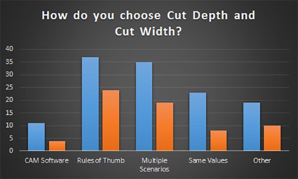
What’s the most important factor almost nobody tries to optimize? (Cut Depth and Cut Width)
Here’s a really important insight about the performance of your CNC cutting tools–it depends tremendously on your choice of Cut Depth and Cut Width. Everything else is pretty cut and tried, or whatever isn’t will depend on the Cut Depth and Cut Width. Your cutter’s performance, the performance of your HSM toolpath, your surface finish, your tool wear–all of these are hugely affected by your choice of Cut Depth and Cut Width.
Despite how important these parameters are, we often put the cart before the horse. We choose Cut Depth and Cut Width in some haphazard fashion, plug them into the Feeds and Speeds Calculator as givens, and expect good things to happen.
Here’s what our survey of CNC’ers told us about how folks are choosing the Cut Depth and Cut Width:
Rules of thumb? Use the same values each time? Divining rod?
The thing is, none of those methods will optimize Cut Depth and Cut Width. Let me clarify what I mean–to optimize is to try to maximize one or more variables while minimizing any bad properties. Here are some potential things to optimize or avoid when selecting Cut Depth and Cut Width:
Use as much flute length as possible–it maximizes tool life by spreading the wear over more of the cutting edge. It also improves surface finish by minimizing the lines on the wall from the tip of the cutter.
Keep Feeds and Speeds in line with what’s good for the tool. You will have to go slower if you use a deeper Cut Depth or a wider Cut Width.
Get as much Material Removal Rate as possible. After all, removing material is what roughing is all about. But, balance this against the Feeds and Speeds. There are some combinations that are more optimal than others.
Keep tool deflection under control. Too much deflection will ruin accuracy, reduce tool life, and possible result in chatter, which is terrible for finish and tool life.
I could go on, but that’s already a lot of balls to juggle. Optimizing Cut Depth and Cut Width isn’t easy unless you have the right tools. Guess what (you knew I was going to say this), G-Wizard has the right tools–in fact there are two different tools built in to help you with it.
First is the Cut Optimizer. Pick a variable to hold constant. Perhaps you need to slot with full cutter width and want to optimize the cut depth. G-Wizard will do that. Set the width and click the optimizer button next to depth and you’ll have your answer. Or vice versa–lock the cut depth to be the full depth of the pocket and maximize the cut width. A couple of clicks and you’re there.
G-Wizard can go one better though–CADCAM Wizards will optimize it all after asking just a few questions. Let’s say you’re cutting a pocket. It needs to know the pocket’s depth and the minimum inside corner radius. From these it will give you a complete optimized recipe for roughing and finishing that includes:
Suggested tool
Feeds and Speeds
Cut Depth and Width
CADCAM Wizards work by using some very sophisticated algorithms to test 600-800 scenarios using the G-Wizard Feeds and Speeds engine. It does this in a couple of seconds. Now when was the last time you considered 600 different variable combinations while setting up a CAM job? Be honest!
Everything you need to know to set up your CAM toolpath from just 2 questions–now that’s efficient!
Organize Your Tooling Information
Tooling information–what a mess!
It’s in spreadsheets, CAM Software, yellow pads, post it notes, and machine tool tables. Is any of it up to date? Is all of it in sync? Ever spend a bunch of time in CAM only to discover you didn’t have the tools called for even in inventory? Ever launch a job that had the wrong tools in the changer compared to what the gcode expects?
Get yourself organized and avoid this problem. There are a number of options, but my recommendation if you don’t have something a lot fancier (and a lot more expensive) is to set up a master spreadsheet. Turns out we can even help with that. G-Wizard (Editor and Calculator) can import and export Tool Tables in csv (spreadsheet) format.
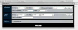
There’s even a nifty utility called the “Crib Wizard” that will pre-populate the table with standard sizes:
Using Crib Wizard you’ll have one or more master spreadsheets ready to go in no time. Now just one more tip–we’ll be adding tons of powerful new features to Tool Cribs during 2016. They can already be shared in a common folder across applications. We’ll also be adding the capability to export in common CAM software formats. Once that’s there, keeping all the tables synchronized will be easy. Until then, keep the spreadsheet handy!
#2 Try Some New Approaches to Fixturing and Setup
OK, let’s say you’ve got CAM working so smoothly it’s a finely oiled machine. Next up is Fixturing and Setup. I’m going to focus on aids to quick setup rather than fixturing large numbers of parts. Quick Setup is advantageous for the small lots that are so common these days.
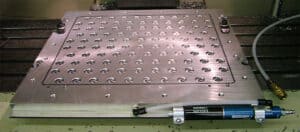
Discover Vacuum Fixturing
Vacuum Fixturing is slick, easy to use, and the perfect solution for many workholding problems. Learn more about it from our overview article. For small parts and plate style parts, it’s the bee’s knees. Unless there is a large surface area available, it can’t take the cubic horsepower of some other approaches, but when it works, it is absolutely fantastic.
You want to have this workholding weapon in your arsenal!
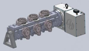
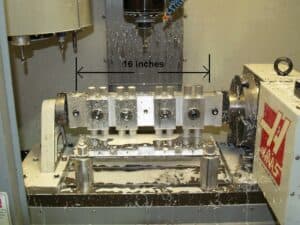
Try a Fourth Axis to Index More Parts
Fourth Axis machining is great stuff–it enables you to solve problems you didn’t think were solvable. For example, how to access both more parts and more positions on parts all in one fell swoop (what the heck is a fell swoop anyway?):
Access more parts and more positions on the parts…
It’s a pretty neat trick. You’d be surprised at what a 4th Axis can do. For example, check this out:
I never would have guessed it, but Geof on CNCZone says the following 4-axis mill set up was able to machine these aluminum bars to length, ensure the faces were square, and drill and tap a hole faster than he could do it in a lathe.
This kind of 4th Axis programming is pretty easy to do. It’s called “Indexing” because no cutting happens while the 4th axis is in motion. It is strictly used to bring more parts to bare or to make another side of the part accessible. Not all CAM software can facilitate this kind of thing, so you may have to intersperse a little bit of hand g-code to position the 4th axis and then create a separate CAM-generated g-code program for each position. That’s actually not hard to do, especially if you have a tool like our G-Wizard Editor.
Make 2016 the year you get comfortable with and take advantage of 4th axis indexing.
I had to put something in especially for beginners. Does the 4-jaw chuck scare you? Does it seem cumbersome? Does it take forever to get it dialed in? Is it sitting in a corner gathering dust while the 3 jaw stays permanently on your lathe?
Don’t fret–you need to learn how to dial in a 4-Jaw quickly, and once you do, a lot of other similar operations will seem easier too. To learn how to do it with both a video and a checklist, cruise over to our Lathe Workholding page. You’ll discover it takes longer to explain the process than to do it once you learn how.
BTW, lots of other great stuff on that page starting with the chart at the top that makes it easy to figure out which workholding solution is best for your turning project.
#3 Learn Some Sneaky Tricks That’ll Let You Cheat On the Rules
Sneaky stuff for CNC’ers…
I always loved learning sneaky tricks that break the rules. As soon as someone said, “Never” or “Impossible” I was off looking for ways to skirt the obstacles. These sneaky resolutions can help you cheat in useful situations that come up more often than you’d think.
Use 4 Flute Endmills in Aluminum
Once upon a time, machinists were taught never to use more than 2 fluted endmills in aluminum. The reason is that aluminum’s high chip loads coupled with the way the chips curl make for larger chips than other materials. There’s not enough space between the flutes to carry the stuff away if you’re not careful and a 4 flute quickly jams and breaks if you just dive it into aluminum.
Now here’s the trick–if your Cut Width is extremely small relative to the diameter, you can get away with more flutes. There’s enough room there to allow it to work. I often use 4 flutes for light finishing passes, for example.
Why?
Because having more flutes is like having a faster spindle. 2x the flutes = 2x the feedrate at a given rpm. Or, if you keep the same feedrate, it’s like having 2x the rpm and a much nicer surface finish.
Just make sure you’ve got coolant or mist lubricating the cutter. With 4 flutes the aluminum is even more likely to weld on.
Use HSS When It Performs Better than Carbide
Doesn’t everyone know that Carbide is far better than HSS? Well, they think they do, but there are cases where it is not. The thing is, Carbide can handle higher rpms because it can stand much higher temperatures than HSS. But HSS tolerates higher chip loads than Carbide. Typically it can also get sharper edges. Carbide is less likely to flex (i.e. for Tool Deflection) but HSS can withstand more flex before it breaks.
If we put all of this together and search for cases where the strengths of HSS can shine and the strengths of Carbide aren’t in play, we find those cases where HSS outperforms Carbide. Let’s talk about a few.
If you’re limited by spindle speed in a soft material, the higher chip load of HSS can mean higher Material Removal Rates than for Carbide. In other words, that HSS will hog better than your fancy Carbide. Whoa!
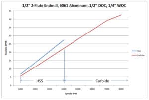
Here’s a chart generated with G-Wizard Calculator values that shows the relationship:
For a 1/2″ 2 Flute Endmill, you’re better off with HSS if your machine won’t go faster than 4000 rpm. We have an article that deals with this in more depth. Suffice to say, you want to check your options if you think you’re rpm-limited at all.
HSS is faster at removing material in some cases, but here is another–it can have better Tool Life too! OK, now this really kills folks to think about because Carbide is so much tougher. How the heck can HSS last longer? The answer is that it is less brittle. If you must have a fair amount of deflection or runout relative to the chip load, try an HSS cutter. It will tolerate more before it breaks. This is primarily going to be of use to hobbyists who have spindles with a lot of runout, but pros can sometimes find it a useful edge case too. The trick will be the tradeoff between the extra rigidity of the carbide and the ability of the HSS to take more of a beating.
The resolution is to be alert to possibilities where HSS may be Carbide.
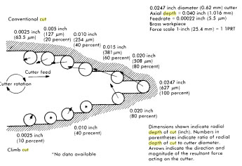
Be Alert to the Advantages of Conventional Over Climb Milling
Did he just get that backwards?
Let me say it differently: CNC’ers are used to Climb Milling everything. It’s one of the special things they get to do that most manual machinists can’t. And it often produces great results. It’s the better choice in the majority of situations, but not in every situation. We have a whole article on Climb vs Conventional Milling in our free Feeds and Speeds Cookbook, but let me summarize the two sneaky things to be aware of.
First, some clever folks over at Dapra realized a long time ago that when Cut Widths are larger than a certain percentage, Climb Milling changes the geometry of the cutting edge. In fact it tilts that geometry to the point it acts more like negative rather than positive geometry. Who knew?
Well, the good news is that we’ve built Dapra’s observations into G-Wizard Calculator and it will actually tell you when to use Conventional Milling in your cut.
Tool Deflection for Climb vs Conventional Milling…
The Second Sneaky Thing is all about Surface Finish. It boils down to knowing that when Climb Milling, the tool will tend to deflect into the wall of the material while when Conventional Milling the tool will tend to deflect along the path the tool is following. Mind you, the cutting forces are less with Climb than Conventional, but if they are high enough that deflection is a possibility, you’ll get the better finish with Conventional Milling!
This is not one that can be easily predicted, you just have to try it both ways on a job and see which one looks better. But, you can use a tool like G-Wizard to tell you what the deflection is and keep that in mind together with your test results to figure out which one to choose in the future.
Master Chatter and Tool Deflection So They Trouble You No More
Chatter and Tool Deflections–these are Black Arts for CNC’ers if ever there was such a thing. But just a little knowledge can go a long ways towards taming these Beasts.
Let’s take Tool Deflection first, because it is simpler. Tool Deflection is a function of three variables:
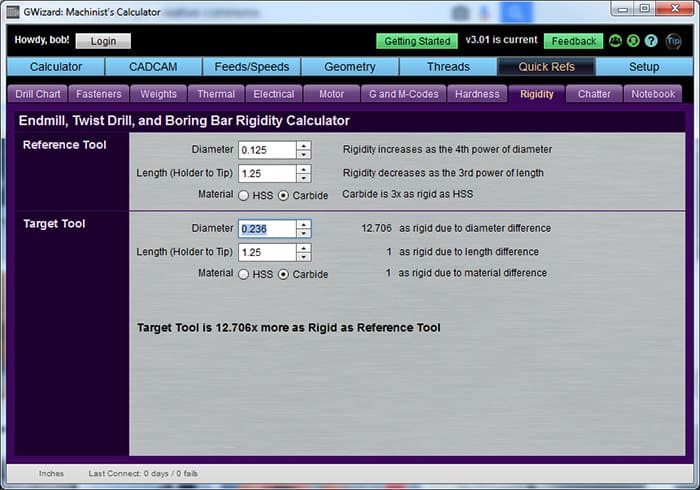
Tool Material: Carbide is 3x as rigid as HSS
Tool Stickout: How far from tip to where the tool is supported in the Tool Holder? Rigidity decreases as the 3rd power of length.
Tool Diameter: Rigidity increases as the 4th power of length.
To combat Tool Deflection, you must use a stiffer material, reduce stickout, or increase tool diameter. If you can’t then you have to back off feeds and speeds so the forces on the tool are reduced. All that 3rd and 4th power math means small changes can really make a big difference. Say we have a 1/8″ Endmill being asked to work with a stickout of 1 1/4″. If we can switch to a 1/4″ Endmill, the rigidity goes up 16x!
OK, now let’s do something sneaky. Suppose 1/4″ just won’t fit. But we have a kind of an odd-sized endmill on hand, a 3/16″. It’s over 5x more rigid and may save the day. Let’s get even sneakier. We’re cutting a part with Imperial dimensions, but we have a box of metric endmills handy. That 1/4″ is still too big, but we happen to have a 6mm endmill. It’s 12.7x as rigid. Having those odd sizes available can really help in deflection challenged situations.
Here’s two important two that also help. First, G-Wizard’s Feeds and Speeds will calculate deflection and will optimize away from it as we have already discussed. But, there’s also a handy rigidity calculator built in:
G-Wizard’s Rigidity Calculator…
It’s what I used to come up with all those numbers. One more Deflection Resource worth looking at is our article Tool Deflection Control: Critical for Your Success. It’s a quick read and guaranteed to make you the expert on Tool Deflection among your CNC buddies.
What about Chatter?
Ouch! Machinists hate it! It’s loud, unpleasant, and a sure sign something really terrible is about to happen. Our instinct is to dial way back on rpms or feedrates (hopefully both, if you cut rpm and leave the same feedrate chip loads soar and you’ll break a tool before too long).
But guess what? Your instinct is only half right.
Chatter is a resonance phenomenon. When the spindle is at the right speed, the resonance is maximized and amplified. Like feedback in the microphone of your local garage band–another horrible screech. What that means is that it may be just as good to speed up as to slow down. You just have to find an rpm range that minimizes the chatter.
Chatter is repeatable, given the same set of variables. Those variables are:
Which machine it happened on
What kind of toolholder
What kind of cutter
How much cutter stickout
What rpms
If you experience chatter, note down those variables. If we duplicate those variables and apply enough cutting force, we’ll get chatter again because the variables are the same.
We can eliminate chatter in one of two ways. First, we can make everything more rigid, which will fight the chatter. Or second, we can change the variables until the chatter goes away. The easiest thing to change is rpms followed by stickout. Keep good notes on where your chatter occurs and you can avoid the dangerous combinations going forward.
BTW, serrated roughing cutters are much less prone to chatter and may be another good answer. If nothing else they can also cut quite a bit faster than conventional end mill, so it’s hard to lose with one.
We have a whole chapter on how to manage chatter too. You can either discover it piecemeal as it happens in the course of your work, or we tell you how to systematically map out the chatter zones. It’s much less of a Black Art once you have a little information on how it works and how to deal with it.
Bonus 4th Category: Learn some skills that are rare among CNC’ers
There you have it, CNC’ers–some great ideas for New Year’s Resolutions. They basically boil down to learning some new techniques or tools that will increase your productivity quite a lot. Tell what New Year’s Resolutions you’re making as a CNC’er in the comments below–we’d love to hear from you!
Like what you read on CNCCookbook?
Join 100,000+ CNC'ers! Get our latest blog posts delivered straight to your email inbox once a week for free. Plus, we’ll give you access to some great CNC reference materials including:
Bob is responsible for the development and implementation of the popular G-Wizard CNC Software. Bob is also the founder of CNCCookbook, the largest CNC-related blog on the Internet.


Wow. That is a very interesting and useful list. And persuasive. Thanks.